Production Testing
Overview
The purpose of the test procedure is to identify connectivity issues, poor ICs/passive components soldering, and potential manufacturing defects. Some of the issues are directly identified by explicit, part targeted tests, others are implicit, by running adjacent tests.
Test Duration
Step Description |
Estimate Time |
|---|---|
Test system initial setup |
30 min |
Hardware setup and testing per system |
5 min |
Test Requirements
Devices Under Test (DUTs)
T1L Ethernet cable
Testing Equipment
1 x AD-SWIOT1L-SL board (used as a reference)
1 x AD-T1LUSB2.0-EBZ board (used as a reference)
MAX32625PICO (Daplink programmer)
Usb A to Micro-Usb cable for the Daplink programmer
Raspberry Pi 4 + Power supply
Mouse and keyboard for Rpi
Micro HDMI cable for Rpi
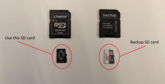
2 x SD card with test software for the Rpi
Loopback terminal block
24V power supply
HDMI Monitor
Test Setup
Insert the SD card into the Rpi (use the one highlighted in the second image below, not the backup card).
Connect the MAX32625PICO (Daplink programmer) to the Rpi using a Usb cable.
Connect the HDMI cable to the Rpi (HDMI 0 port) and display.
Connect the keyboard and mouse Usb dongle into the Rpi.
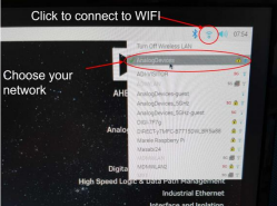
Plug an Ethernet cable into the Rpi for internet access. If a wired LAN is not available, Wi-Fi can be used by following the steps from the Enabling Wi-Fi on the Raspberry Pi section below.
Insert the power cable into the Rpi.

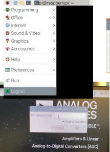
Enabling Wi-Fi on the Raspberry Pi
Note
This step is required only if a wired LAN connection with internet access is not available for the Raspberry Pi.

Testing Procedure
Hardware Setup
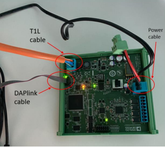
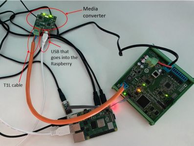
Connect the MAX32625PICO (Daplink programmer) to the AD-SWIOT1L-SL (DUT) using the ribbon cable.
Connect the T1L cable (DUT) into the AD-SWIOT1L-SL (DUT).
Connect the T1L cable (DUT) into the AD-T1LUSB2.0-EBZ (DUT).
Connect a Usb cable to the AD-T1LUSB2.0-EBZ (DUT) and plug the other side into the Rpi.
Connect the 24V power supply into the AD-SWIOT1L-SL (DUT).
Running the Test Software
After the Raspberry Pi boots, the test screen will appear on the monitor as shown below.

Attention
If at any point a test fails, you should retry the test suite up to 3 times.
1) Memory/MAXQ1065 Tests
Type 1 into the terminal then press ENTER to start the “1) Memory/MAXQ1065 tests” test suite.
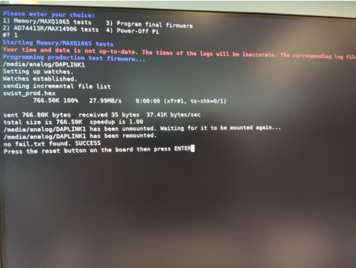
If the firmware is successfully written, you should see the “no fail.txt found. SUCCESS” message on the screen.
Press the RESET button on the board (see below).
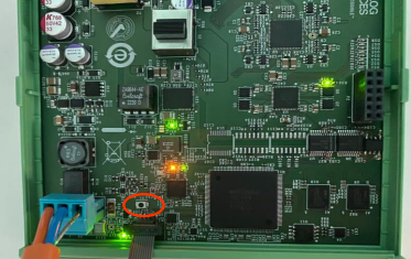
Press ENTER on the Rpi keyboard to continue.
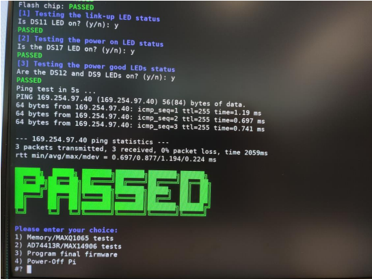
Next, the tests for “UART”, “MAXQ1065”, “RAM chip 1”, “RAM chip 2” and “Flash” will automatically run, without the need to intervene. The test results will appear on the screen.
If the previous tests are successful, you will be prompted to visually check if some LEDs are on. Type “y” for yes or “n” for no. You may associate their name with the silkscreen of the AD-SWIOT1L-SL board.

In case the LED tests are successful, but the ping test fails, swap the AD-T1LUSB2.0-EBZ (DUT) with the reference AD-T1LUSB2.0-EBZ, and run the test again:
If the ping test still fails, the current AD-SWIOT1L-SL (DUT) would be considered to have failed the testing.
If the ping test is successful, the AD-T1LUSB2.0-EBZ (DUT) is considered to have failed the test and should be replaced with another AD-T1LUSB2.0-EBZ (DUT) and restart system testing from the beginning.
If the test passed successfully, the PASSED message will appear on the screen. Proceed to the next test.
2) AD74413R/MAX14906 Tests
Warning
It is very important to start running the next tests without the loopback terminal block connected. It should be attached once you are prompted to do so.
Type 2 into the terminal to start the “2) AD74413R/MAX14906 tests”.
If any of the tests fail, you should restart the test up to 3 times. Make sure to disconnect the terminal block first.
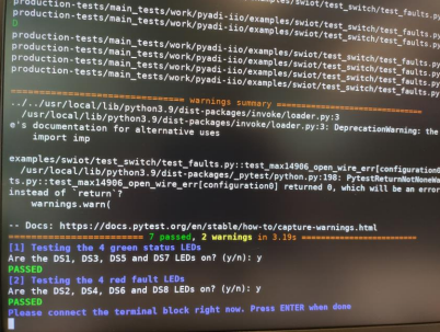
You will be prompted to visually check if some LEDs are on. Type “y” for yes or “n” for no.
Testing the 4 green status LEDs: Are the DS1, DS3, DS5 and DS7 LEDs on?
Testing the 4 red fault LEDs: Are the DS2, DS4, DS6 and DS8 LEDs on?

After the faults test is done, connect the terminal block and press ENTER on the Rpi keyboard to run the next tests.
If the tests are successful, the PASSED message will appear.
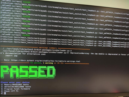
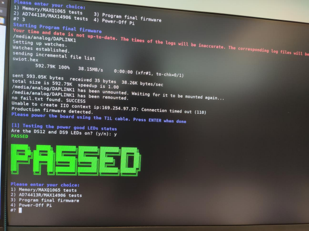
3) Program Final Firmware
Type 3 into the terminal to run “3) Program final firmware”.
With the hardware connections as they are, wait for the firmware to be written.
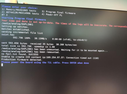
If firmware programming is successful, it should show the “no fail.txt SUCCESS” message being printed.
If this step is unsuccessful, a “FAILED” message will appear. In such case, retry this test up to 3 times.
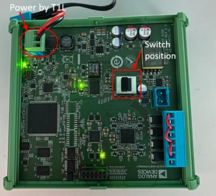
Unplug the power cable from the AD-SWIOT1L-SL board and power it using the T1L connector of the power supply as shown.
Make sure the switch is in the position highlighted below (marked as “INTERNAL POWER SUPPLY” on the silkscreen next to the S2 switch).
You should visually check if 2 LEDs are on (DS12 and DS9). Type “y” for yes or “n” for no.
If the test passed successfully, the PASSED message will appear.
After Testing
Power off the AD-SWIOT1L-SL board by unplugging the T1L cable.
Flip the S2 switch in the “EXTERNAL POWER SUPPLY” position (as highlighted by the silkscreen near the switch).
Disconnect the terminal block so it may be used for the next DUT.
Proceed to the next untested DUTs and repeat the testing procedure.
When done testing all the DUTs, type 4 in the terminal to power off the Rpi.