Production Testing
Overview
The purpose of the test procedure is to identify connectivity issues, poor soldering, and potential manufacturing defects. Some of the issues are directly identified by explicit part-targeted tests, others are implicit, by running adjacent tests.
Test Duration
Step Description |
Estimate Time (minutes) |
|---|---|
Test bench setup |
5 min |
Software test |
4 min |
Total time |
9 min |
Test Requirements
Required Hardware
Raspberry Pi 4 with power supply
SD card
Monitor
Mini HDMI cable
Usb keyboard
DUT - PQM board assembly (main board + front panel)
New empty SD card for SD test
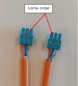
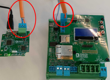
T1L cable, not crossed (see image below)
T1L Usb adapter (AD-T1LUSB2.0-EBZ)
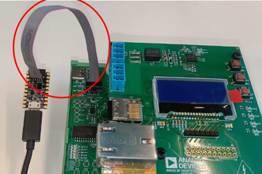
MAX32625PICO (Daplink programmer) with MAX32650 Daplink firmware
MAX32625PICO ribbon cable
1 x Usb Type-A to Usb Type-C cable (for DUT power)
2 x Usb Type-A to Micro-Usb cable (for T1L Usb, Daplink)
Required Software
The test image is provided on a pre-configured SD card.
Required Setup
Insert the SD card into the Raspberry Pi.
Connect the Raspberry Pi to the monitor using the Mini HDMI cable.
Connect the USB keyboard to the Raspberry Pi.
Assemble the DUT by inserting plastic standoffs on the main board and connecting the front panel to the main board.
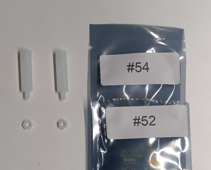
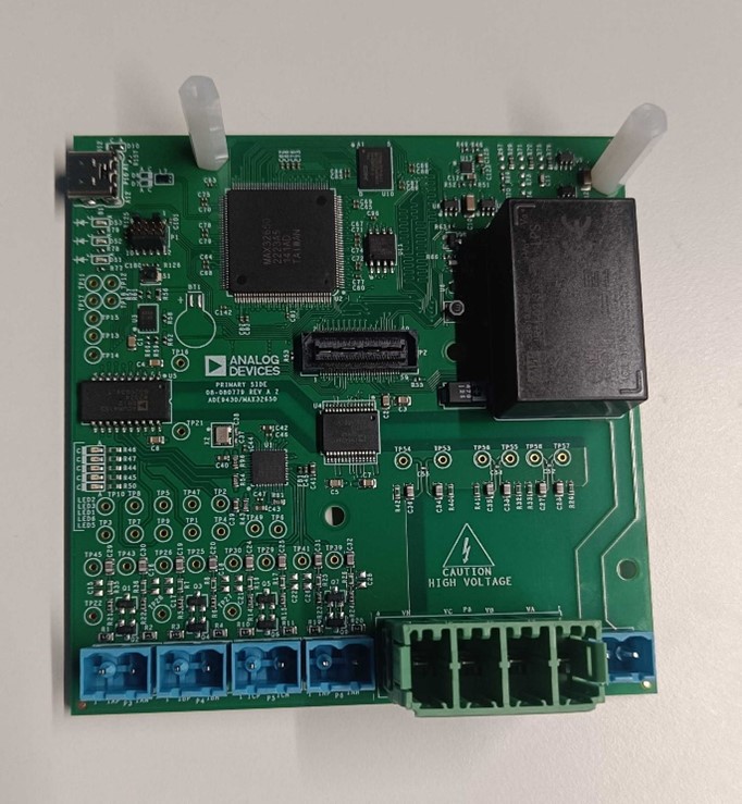
Figure 4 Main board with fasteners attached. Two plastic standoffs and hex nuts are attached to the shown mounting holes.
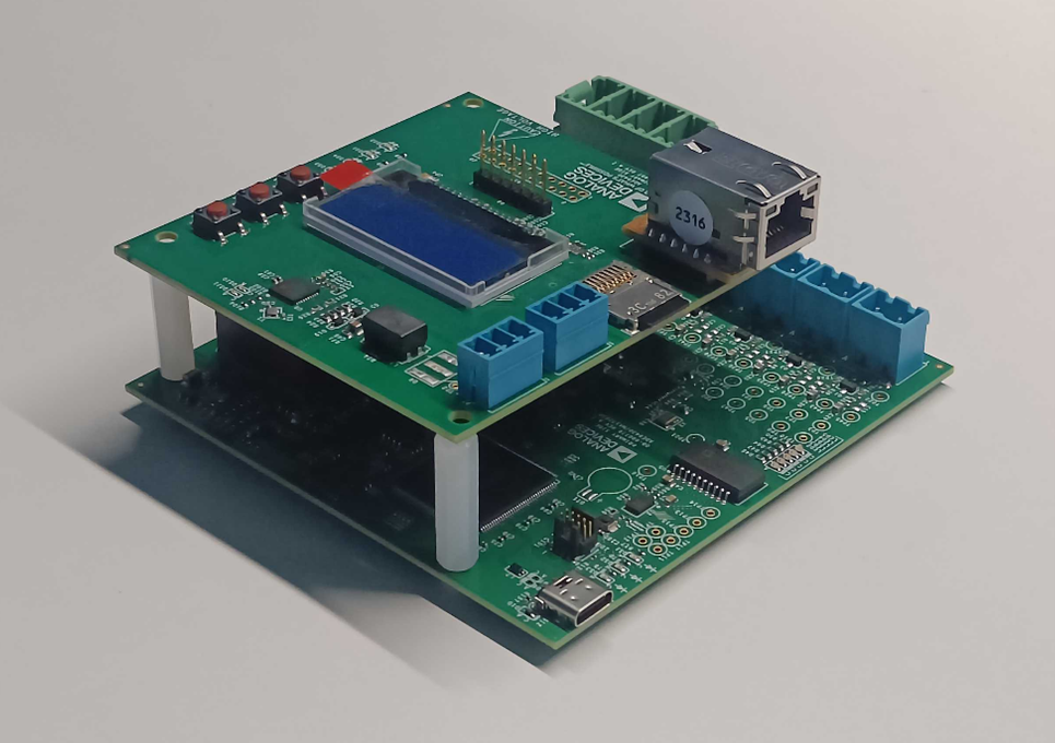
Figure 5 Complete board assembly. The secondary board does not attach to the 2 standoffs with screws, it just passively rests on them.
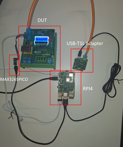
Connect Daplink to Raspberry Pi (via Micro-Usb cable) and DUT (via ribbon cable).
Connect T1L Usb to Raspberry Pi (via Micro-Usb cable) and DUT (via T1L cable).
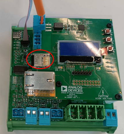
Insert the SD card into the SD slot of the Add-on board.
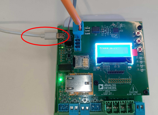
Connect the DUT to the Raspberry Pi (via Usb-C cable).

Test Process
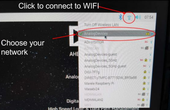
Wi-Fi Setup
Before starting the testing procedure, make sure the Raspberry Pi is connected to Wi-Fi.
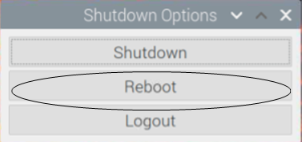
Running the Test Software
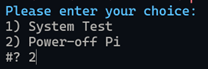
After the Raspberry Pi reboots, the test screen will appear on the monitor as shown below.
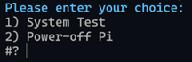
1) System Test
Type 1 and press ENTER to erase DUT flash and begin the system test.
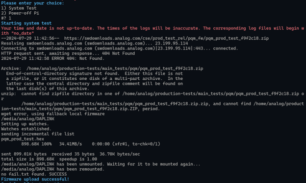
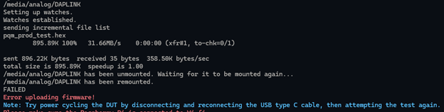
Attention
If the test fails early with error message “Error uploading firmware”: Try disconnecting the Usb-C cable that powers the DUT, reconnecting, and running the test again. You should get the message “Firmware upload successful!”
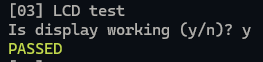
LCD Test
Wait for test step 3 (LCD Test). Check if the LCD display shows the message “Press y…”.
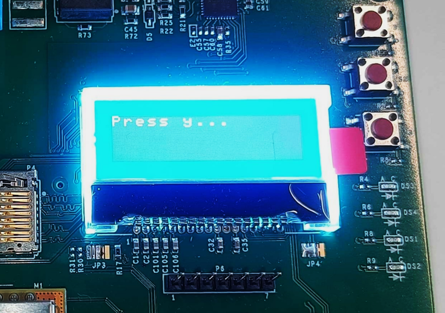
If the message appears, press Y key.
If it does not appear, press N key.
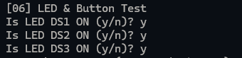
LED and Button Test
Wait for test 7 (LED & Button Test). Check if LED DS1 is ON.
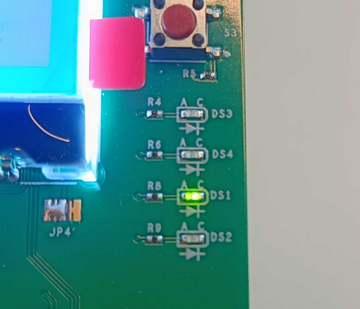
If LED DS1 is ON, press Y key.
If it is OFF, press N key.
Repeat this step for LEDs DS2, DS3.
Wait for the message “Press button S1! (5 second timeout)”. Press button S1 (duration does not matter). Repeat for buttons S2, S3.
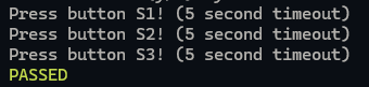
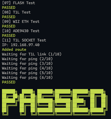
The remaining tests will run automatically. Wait for the final PASSED or FAILED message.
After testing a board, disconnect power, T1L, and the ribbon cable, and continue with the next board.
2) Power Off
When you are done testing, type 2 and press ENTER to power off the test bench.