Production Testing
Overview
The purpose of the test procedure is to identify connectivity issues, poor soldering, and potential manufacturing defects.
Test Duration
Step Description |
Estimate Time (minutes) |
|---|---|
Test bench setup |
5 min |
Software test |
1 min |
Total time |
6 min |
Test Requirements
Required Hardware
1 x AD-SWIOT1L-SL board
24V power supply for the AD-SWIOT1L-SL board
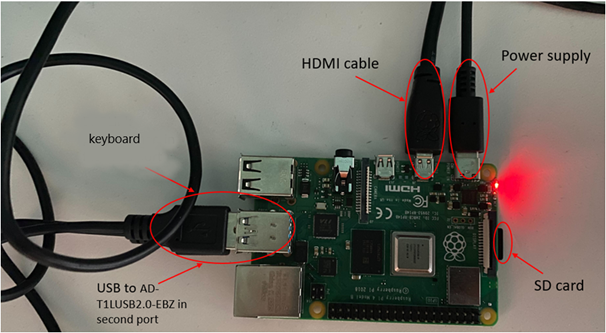
Raspberry Pi, power supply, Mini-HDMI cable
Mouse and keyboard
T1L-to-Usb cable and AD-T1LUSB2.0-EBZ (media converter) as Device Under Test (DUT)
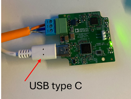
Usb-A to Type-C cable for the media converter
Required Software
The test image is provided on a pre-configured SD card.
Required Setup
Insert the SD card into the Raspberry Pi and power it.
Connect the HDMI cable between Rpi and the monitor, insert mouse and keyboard dongle into the Rpi’s Usb port.
Connect the T1L-TO-Usb cable into the AD-SWIOT1L-SL and into the AD-T1LUSB2.0-EBZ (media converter).
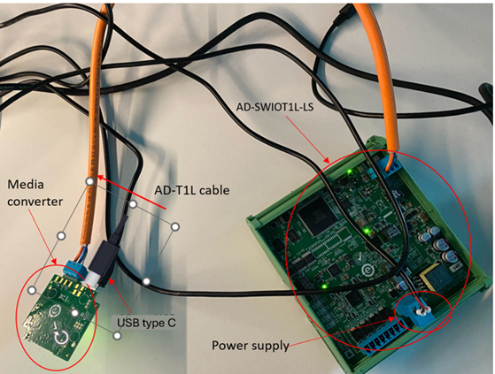
Connect a Usb Type-C cable to the media converter and plug the other side into the Raspberry Pi.
Power the AD-SWIOT1L-SL.
Test Process
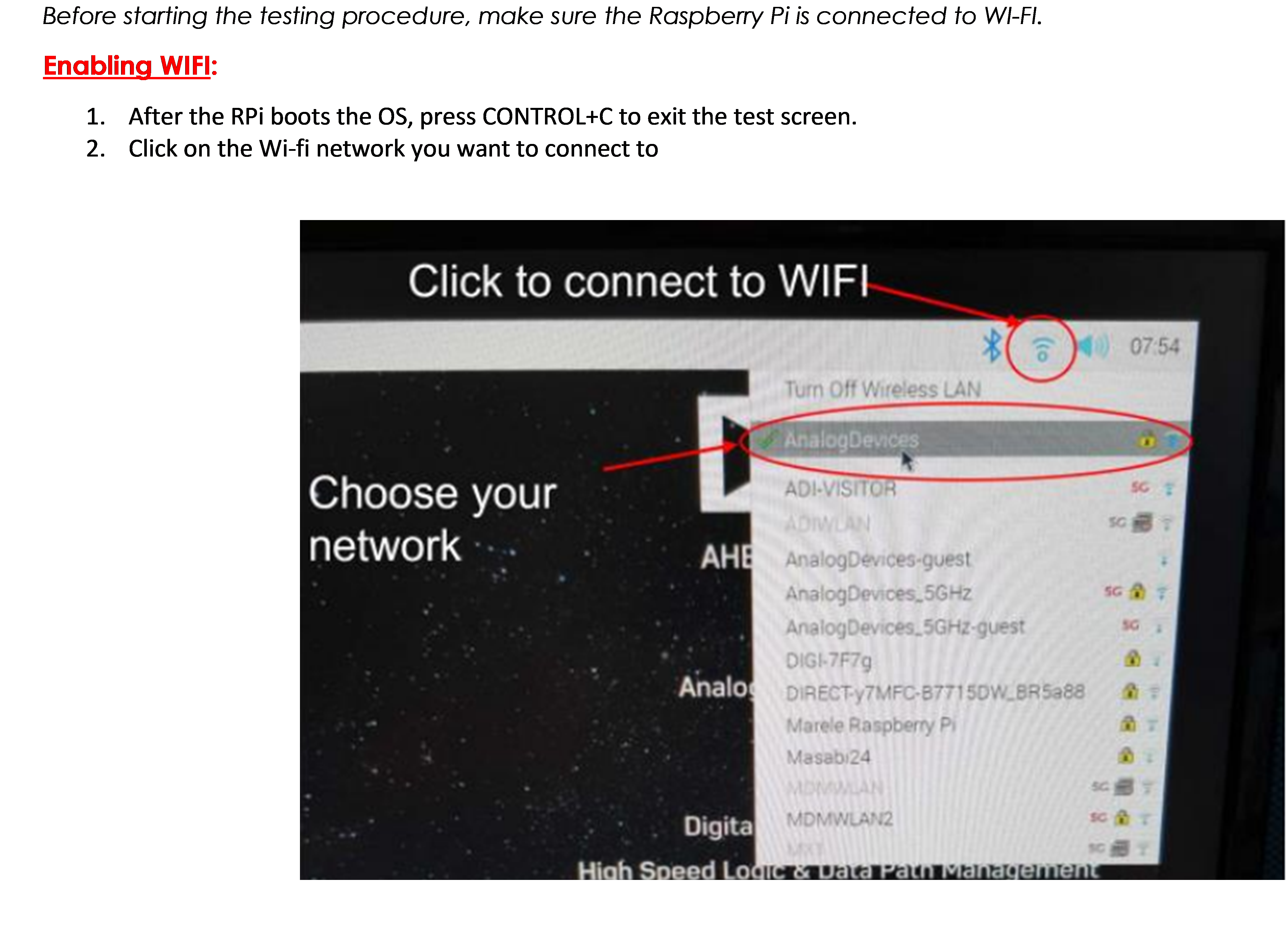
Wi-Fi Setup
Before starting the testing procedure, make sure the Raspberry Pi is connected to Wi-Fi.
Running the Tests
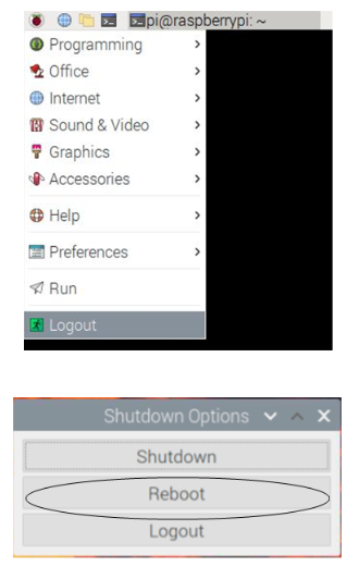
After the Raspberry Pi reboots, the test screen will appear on the monitor.
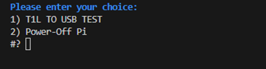
1) T1L TO Usb Test
Type 1 into the terminal then press ENTER to start the “1) T1L TO Usb TEST”.
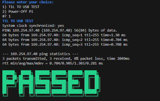
In case a failure occurred, a FAILED message will be displayed.
After the PASSED message is displayed, disconnect the media converter and T1L cable and test the next pair.
Once you are done testing, press 2 and ENTER to power off the Raspberry Pi.