Production Testing
Overview
This document describes the production testing procedure for the AD-GMSL-D-E-ADP board. The procedure focuses on OLDI2HDMI board testing to verify proper GMSL link establishment and video output functionality.
Test Duration
Step Description |
Estimated Time (minutes) |
|---|---|
Test bench setup |
10 min |
Software test |
5 min |
Total time |
15 min |
Test Requirements
Required Hardware
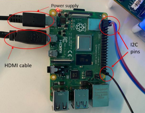
Raspberry Pi 4 + HDMI cable + power supply
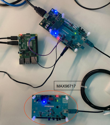
1 x MAX96717 evkit
3 x wires (for I2C connection)
1 x HDMI cable
1 x MAX96752 evkit + power supply
Device under test: AD-GMSL-D-E-ADP (OLDI2HDMI) Board
1 x GMSL cable
2 x external displays
Required Software
SD card with the test image
Required Setup
Insert the test SD card into the Raspberry Pi.
Connect a mouse and keyboard to the Raspberry Pi.
Connect an HDMI cable to the Raspberry Pi and an external display.
Connect the I2C pins from the Raspberry Pi (GPIO 2, 3, 27) to the MAX96752 as shown below. Follow the color-coding cables.
Connect the GMSL cable between the MAX96717 evkit and MAX96752 evkit.
Connect the D.U.T. (AD-GMSL-D-E-ADP) on the MAX96752 evkit as shown below.
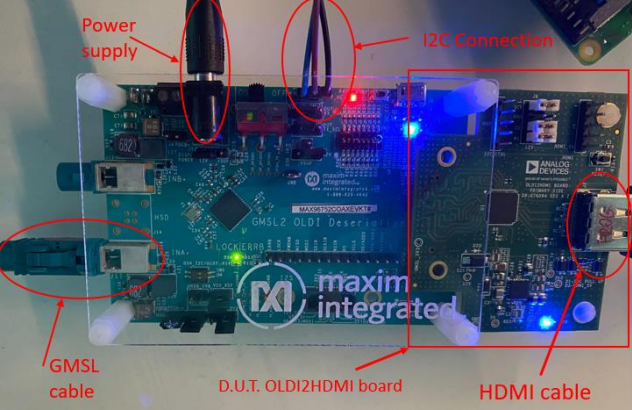
Connect an HDMI cable to the D.U.T. and connect it to a monitor.
Connect the power supply to the MAX96752 and power the board.
Test Process
Wi-Fi Setup
Ensure the Raspberry Pi is connected to Wi-Fi before starting the tests. If the test screen is already running, you will need to exit it first to configure the network connection.
Power on the Raspberry Pi. If the test screen appears automatically, press CTRL+C to exit the test application.
Click on the network icon in the system tray (top-right corner of the screen) to view available wireless networks.
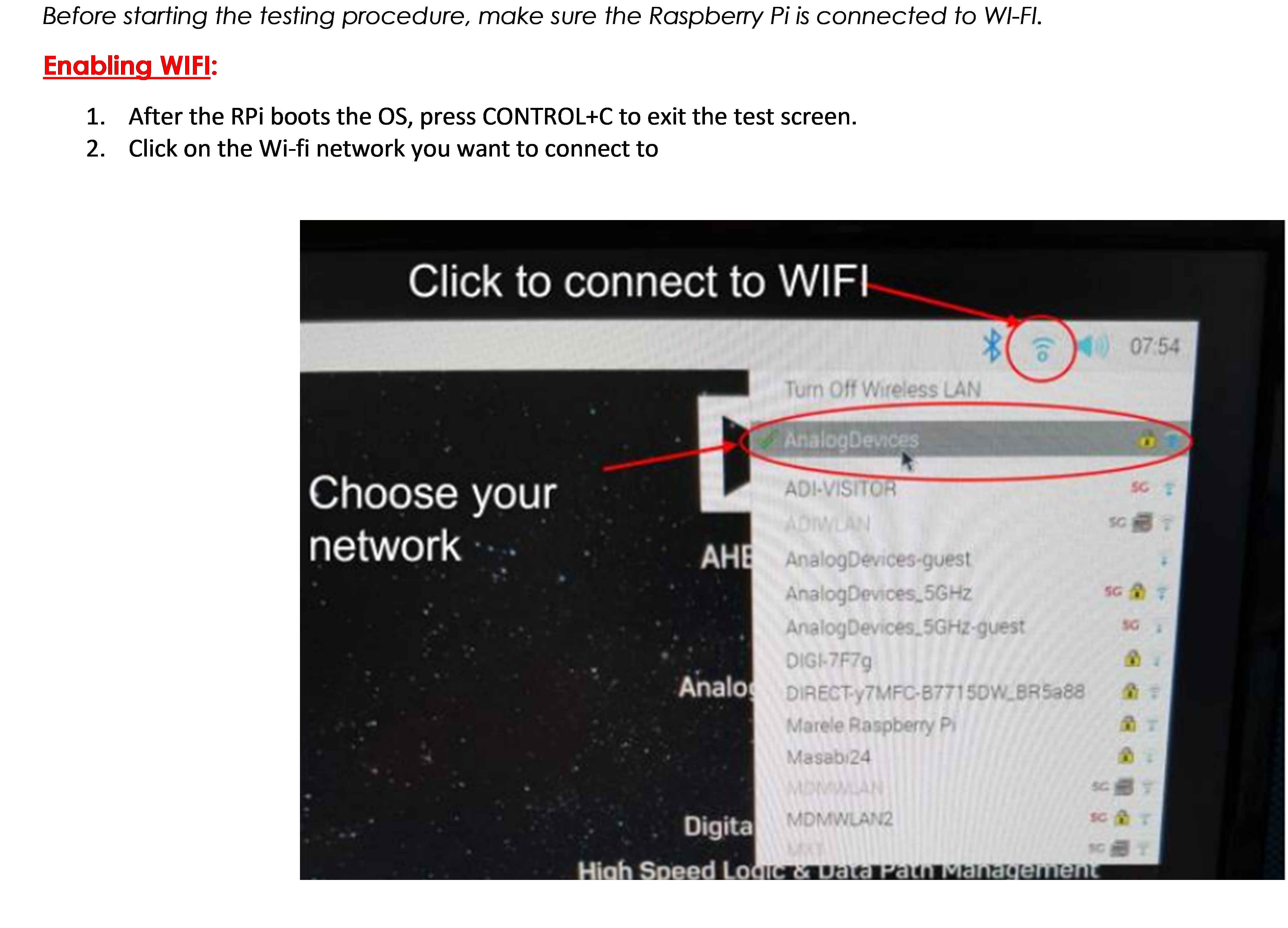
Select your network from the list and enter the password when prompted.
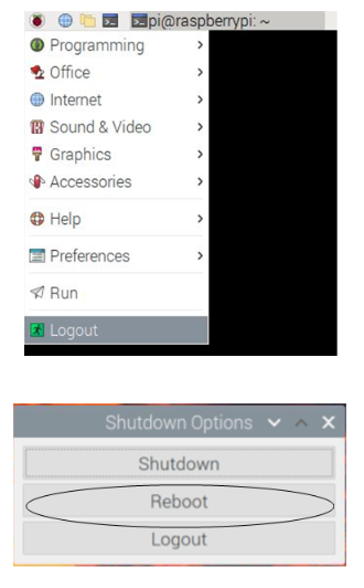
After connecting to Wi-Fi, reboot the Raspberry Pi to reinitialize the test screen. Navigate to the application menu, select Logout, then choose Reboot from the shutdown options.
Running the Tests
After rebooting, the test screen will appear automatically. Make sure the DUT is powered on.
Type 1 from the keyboard to start the GMSL Test.
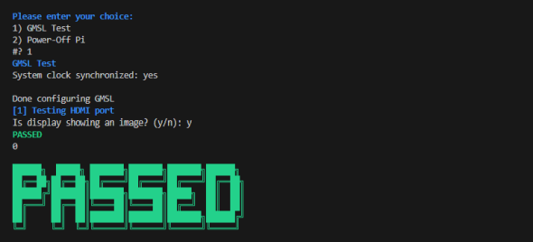
The test will configure the GMSL link and test the HDMI port. When prompted, check if the monitor connected to the D.U.T. displays a color bar pattern.
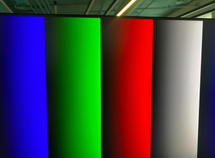
If the display shows the color bar image correctly, type y when prompted.
If the test is successful, you will see a PASSED message on the screen.
To test additional D.U.T. boards, remove the power supply from the MAX96752, replace the D.U.T., power it back on, and repeat the test procedure.
Once you are done testing all boards, press 2 in the terminal to power off the Raspberry Pi.