Production Testing
Overview
The purpose of this test procedure is to identify connectivity issues, poor soldering, and potential manufacturing defects in the AD-ACEVSECRDSET-SL board. Some issues are directly identified by explicit part-targeted tests, while others are detected implicitly by running adjacent tests.
Test Duration
Step Description |
Estimated Time (minutes) |
|---|---|
Test bench setup |
5 min |
Software test |
5 min |
Total time |
10 min |
Test Requirements
Required Hardware
MAX32625PICO (Daplink programmer)
AD-ACEVSECRDSET-SL board
Raspberry Pi 4, power cable, HDMI cable
Mouse and keyboard
Power cable for AD-ACEVSECRDSET-SL board
Required Software
SD card with the test image
Required Setup
Insert the SD card into the Raspberry Pi.
Connect the Raspberry Pi to a monitor and power it.

Connect the MAX32625PICO (Daplink programmer) to the Raspberry Pi and the DUT.
Power the DUT.
Connect the mouse and keyboard to the Raspberry Pi.

Test Process
Wi-Fi Setup
Ensure the Raspberry Pi is connected to Wi-Fi before starting the tests. If the test screen is already running, you will need to exit it first to configure the network connection.
After the Raspberry Pi boots, press Ctrl+C to exit the test screen.
Click on the Wi-Fi icon in the system tray and select the network you want to connect to.
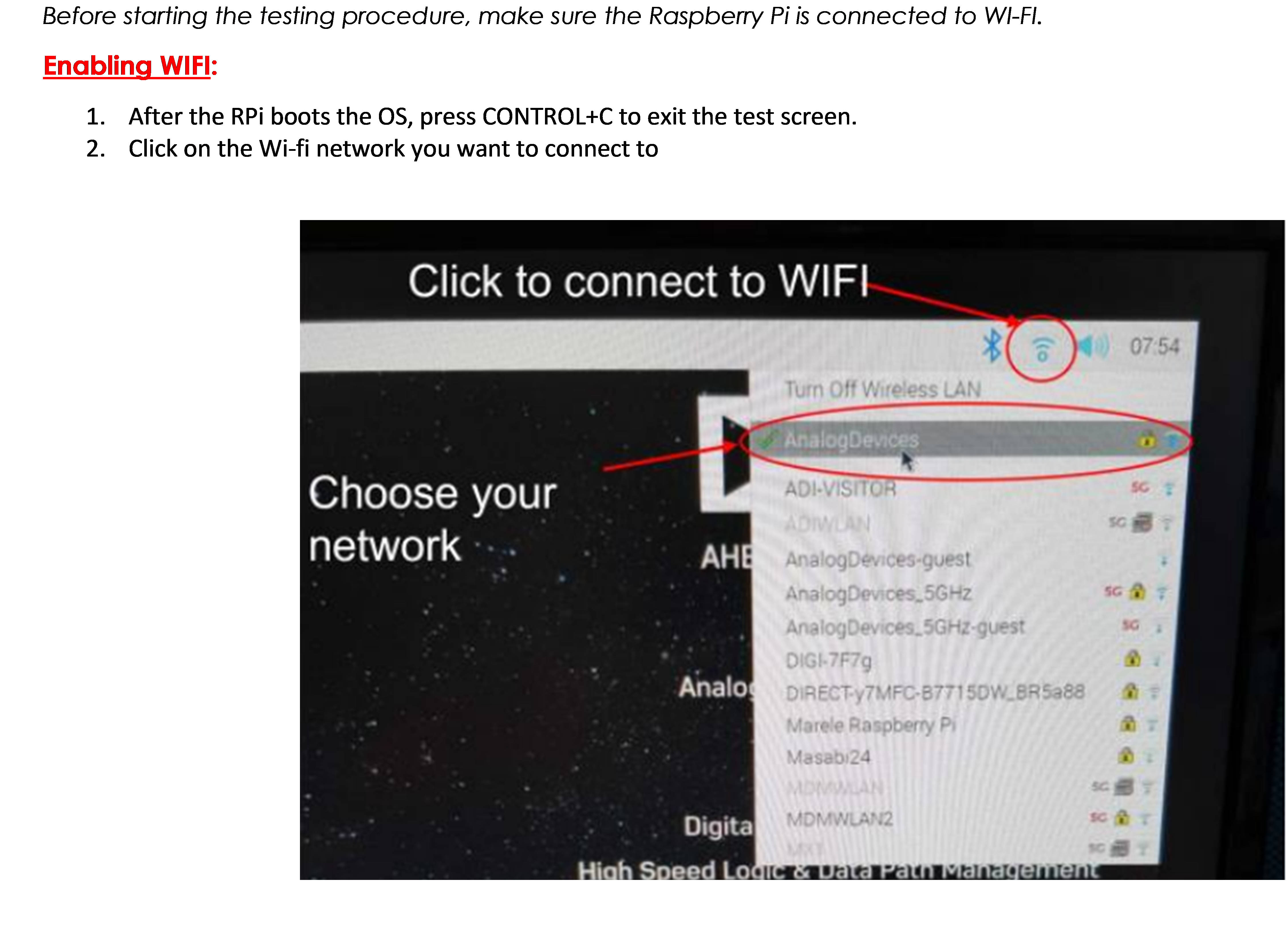
Type in the password and connect to the network.
After connecting successfully, reboot the Raspberry Pi by navigating to the application menu, selecting Logout, then choosing Reboot from the shutdown options.

Running the Tests
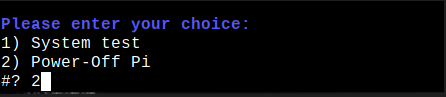
After the Raspberry Pi reboots, the test screen will appear on the monitor.

Type 1 and press ENTER to start the System Test.
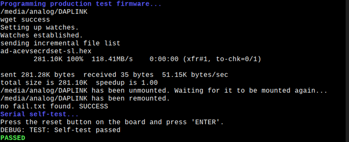
Press the reset button on the board and press ENTER.

Visually check if LED STATUS 1 is on. If all tests pass, you will see a confirmation message.
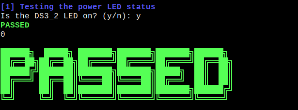
If all tests pass, you can move onto the next D.U.T.
When you are done testing, press 2 and hit ENTER to power off the Raspberry Pi.