Production Testing

Overview

The purpose of this test procedure is to identify connectivity issues, poor soldering, and potential manufacturing defects in the ADRD8012-01Z board. Some issues are directly identified by explicit part-targeted tests, while others are detected implicitly by running adjacent tests.

Test Duration

Step Description

Estimated Time (minutes)

Test bench setup

5 min

Software test

10 min

Total time

15 min

Test Requirements

Required Hardware

  • 1 x ADRD8012-01Z board (device under test)

  • 1 x AMD KRIA KV26 System-on-Module

  • 1 x microUSB to USB cable

  • 1 x SD card for the DUT

  • 1 x wire for UART testing

  • 4 x Digilent Pcam 5C cameras

  • 4 x AD-GMSL716MIPI-EVK (GMSL serializer evaluation kit)

  • 4 x Fakra cables that connect to the DUT board

  • 1 x QNA-T310G1S and SFP+ to thunderbolt cable

  • Power supply for ADRD8012-01Z board

  • 1 x GPIO loopback connector

  • 1 x test laptop and power cable

Required Software

  • Test image provided on the testing laptop

Required Setup

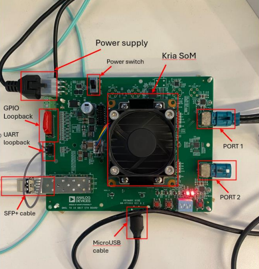
  • Insert the SD card into the ADRD8012-01Z device under test.

  • Attach the KRIA system-on-module on the ADRD8012-01Z.

  • Plug the microUSB cable into the ADRD8012-01Z and into the laptop.

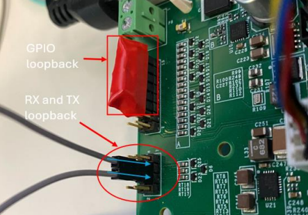
  • Connect the Rx and Tx pins of the UART connector using a wire.

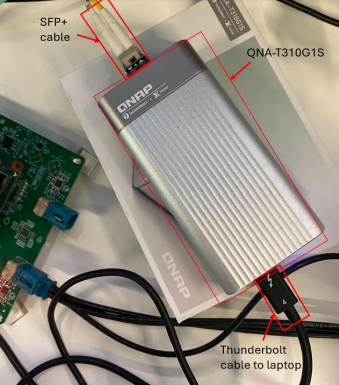
  • Plug in the SFP+ cable into the carrier and into the QNA-T310G1S.

  • Power the QNA-T310G1S using a Type C thunderbolt cable and plug it into the laptop.

  • Attach the GPIO loopback on the GPIO connector.

  • Connect each Pcam 5C camera to an AD-GMSL716MIPI-EVK serializer, then connect each serializer to one of the ports on the quad mini Fakra connector (PORT 2) on the ADRD8012-01Z board.

    https://media.githubusercontent.com/media/plescaevelyn/adi-documentation/adrd8012-01z_prod_test/docs/solutions/reference-designs/adrd8012-01Z/production_testing/images/dut_setup.png

    Figure 1 DUT Setup Overview

    https://media.githubusercontent.com/media/plescaevelyn/adi-documentation/adrd8012-01z_prod_test/docs/solutions/reference-designs/adrd8012-01Z/production_testing/images/loopback_connections.png

    Figure 2 GPIO and UART Loopback Connections

    https://media.githubusercontent.com/media/plescaevelyn/adi-documentation/adrd8012-01z_prod_test/docs/solutions/reference-designs/adrd8012-01Z/production_testing/images/qna_connections.png

    Figure 3 QNA-T310G1S Connections

Test Process

Running the Tests

  • After completing the test setup, power on the test laptop and you will see a login screen.

    https://media.githubusercontent.com/media/plescaevelyn/adi-documentation/adrd8012-01z_prod_test/docs/solutions/reference-designs/adrd8012-01Z/production_testing/images/test_laptop_powerup.png

    Figure 4 Test Laptop Login Screen

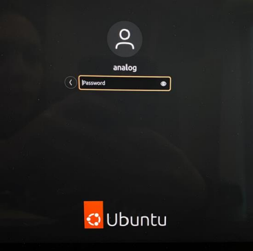
  • Enter the password analog to login.

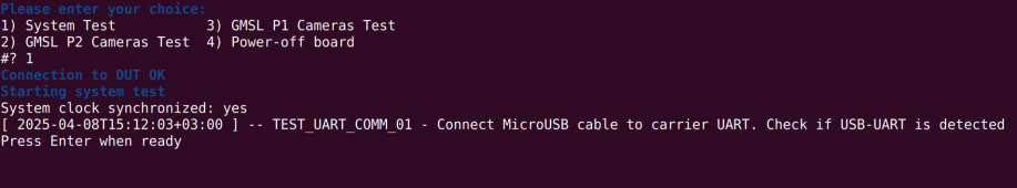
  • When the menu appears, type 1 in the terminal to start the System Test.

    https://media.githubusercontent.com/media/plescaevelyn/adi-documentation/adrd8012-01z_prod_test/docs/solutions/reference-designs/adrd8012-01Z/production_testing/images/test_terminal.png

    Figure 5 Test Menu

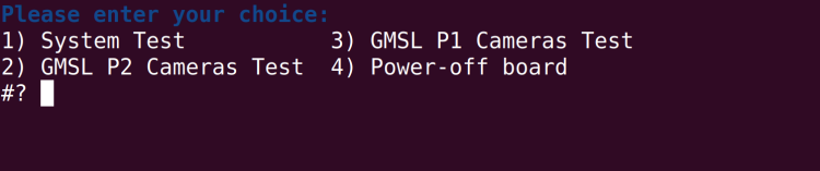
  • Follow the on-screen prompts:

    • When prompted, verify the MicroUSB cable is connected to the carrier UART and press ENTER.

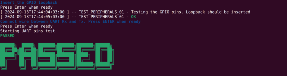
    • When prompted to insert the GPIO loopback, press ENTER.

    • When prompted to connect the wire between UART Rx and Tx, press ENTER.

    https://media.githubusercontent.com/media/plescaevelyn/adi-documentation/adrd8012-01z_prod_test/docs/solutions/reference-designs/adrd8012-01Z/production_testing/images/test_command_1.png

    Figure 6 System Test Prompts

  • If all tests pass, you will see a green PASSED message.

    https://media.githubusercontent.com/media/plescaevelyn/adi-documentation/adrd8012-01z_prod_test/docs/solutions/reference-designs/adrd8012-01Z/production_testing/images/test_command_1_passed.png

    Figure 7 System Test Passed

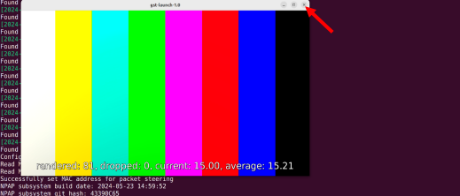
  • Make sure the cameras are connected to PORT 2 and type 2 in the terminal to start the GMSL P2 Cameras Test.

    https://media.githubusercontent.com/media/plescaevelyn/adi-documentation/adrd8012-01z_prod_test/docs/solutions/reference-designs/adrd8012-01Z/production_testing/images/test_command_2.png

    Figure 8 Starting GMSL P2 Cameras Test

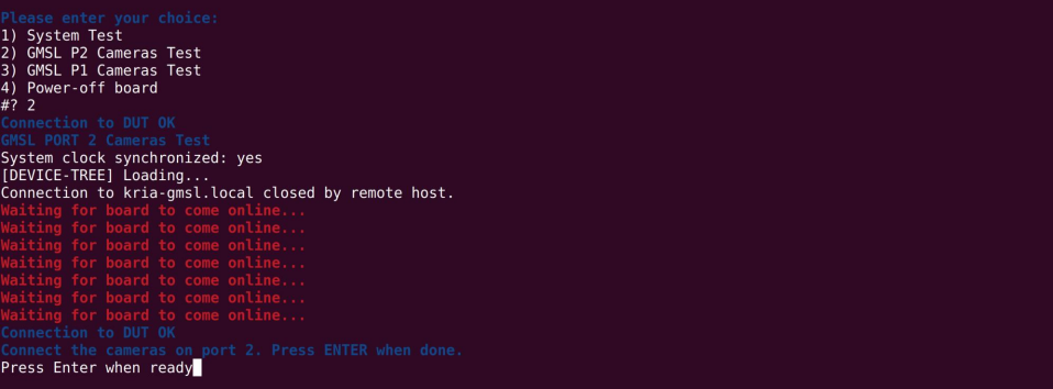
  • The device tree will load and the DUT will reboot. Wait until “Connection to DUT OK” appears.

    https://media.githubusercontent.com/media/plescaevelyn/adi-documentation/adrd8012-01z_prod_test/docs/solutions/reference-designs/adrd8012-01Z/production_testing/images/test_command_2_prompt.png

    Figure 9 Waiting for Board to Come Online

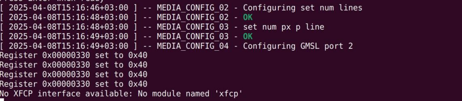
  • When prompted, press ENTER to confirm the cameras are connected to port 2.

    https://media.githubusercontent.com/media/plescaevelyn/adi-documentation/adrd8012-01z_prod_test/docs/solutions/reference-designs/adrd8012-01Z/production_testing/images/test_command_2_pattern.png

    Figure 10 GMSL Port 2 Configuration

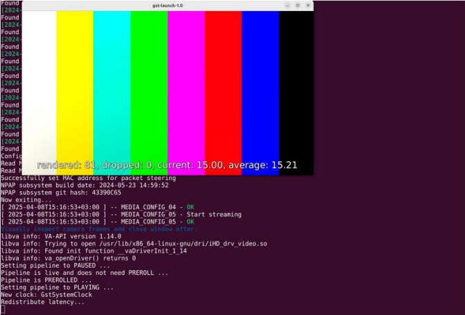
  • If the test passes, you will see a confirmation message.

    https://media.githubusercontent.com/media/plescaevelyn/adi-documentation/adrd8012-01z_prod_test/docs/solutions/reference-designs/adrd8012-01Z/production_testing/images/test_command_2_passed.png

    Figure 11 GMSL P2 Cameras Test Passed

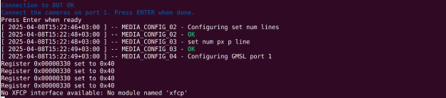
  • Move the cameras to PORT 1 and type 3 in the terminal to start the GMSL P1 Cameras Test.

    https://media.githubusercontent.com/media/plescaevelyn/adi-documentation/adrd8012-01z_prod_test/docs/solutions/reference-designs/adrd8012-01Z/production_testing/images/test_command_3.png

    Figure 12 Starting GMSL P1 Cameras Test

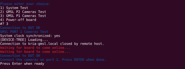
  • Wait for the board to come online and follow the same procedure as for PORT 2.

    https://media.githubusercontent.com/media/plescaevelyn/adi-documentation/adrd8012-01z_prod_test/docs/solutions/reference-designs/adrd8012-01Z/production_testing/images/test_command_3_config.png

    Figure 13 GMSL Port 1 Configuration

    https://media.githubusercontent.com/media/plescaevelyn/adi-documentation/adrd8012-01z_prod_test/docs/solutions/reference-designs/adrd8012-01Z/production_testing/images/test_command_3_pattern.png

    Figure 14 GMSL Port 1 Camera Pattern

    https://media.githubusercontent.com/media/plescaevelyn/adi-documentation/adrd8012-01z_prod_test/docs/solutions/reference-designs/adrd8012-01Z/production_testing/images/test_command_3_prompt.png

    Figure 15 GMSL P1 Cameras Test Result

  • When all tests are complete, type 4 in the terminal to power off the board.