Production Testing
Overview
The purpose of the test procedure is to identify connectivity issues, poor soldering, and potential manufacturing defects. Some of the issues are directly identified by explicit part-targeted tests, others are implicit, by running adjacent tests.
There is only one test fixture that will be used to test three different hardware platforms:
Jupiter Main Board
Jupiter Add-on Board
Jupiter System
Once the initial setup for one of the hardware platforms is done, it is highly recommended that all the hardware platforms of the same type be tested before changing the setup to test another hardware platform. It is mandatory to run the Main Board and Add-on Board tests before System testing because the Jupiter System should include only boards that previously passed the manufacturing testing.
Test Duration
Sequence 1 - Main Board
Step Description |
Estimated Time (minutes) |
|---|---|
Test bench setup |
3 min |
Software test |
10 min |
Total time |
13 min |
Sequence 2 - Add-on Board
Step Description |
Estimated Time (minutes) |
|---|---|
Test bench setup |
3 min |
Software test |
4 min |
Total time |
7 min |
Sequence 3 - System Test
Step Description |
Estimated Time (minutes) |
|---|---|
Test bench setup |
2 min |
Software test |
4 min |
Total time |
6 min |
Test Requirements
Note
Please test all main boards first, then perform the add-on boards testing, and last, test the entire system in the enclosure.
Required Hardware
Initial Setup
1x Raspberry Pi 4 + Power supply |
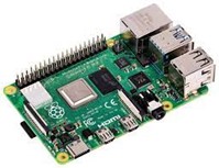
|
1x Micro HDMI cable for Raspberry Pi |
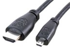
|
1x Mouse and keyboard for Raspberry Pi |
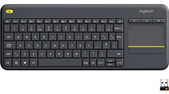
|
1x Test SD card for Raspberry Pi |
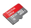
|
1x Portable Display + Power Supply |
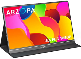
|
1x QR code reader |
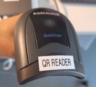
|
RPI PWR shield connection |
|
External Reference Clock and MCS cables |
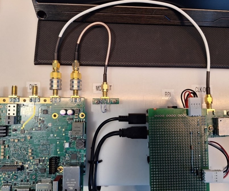
|
Note
1x 4 Port Ethernet Switch + Ethernet cables (3 pieces: 1x 20cm, 1x 50cm, 1 for main switch)
Ethernet switch must be connected to the internet.
1x USB Type A to USB Type C cable
DUT Setup
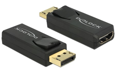
1x HDMI to Display Port adapter |
|
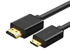
1x Mini HDMI to HDMI cable |
|
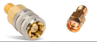
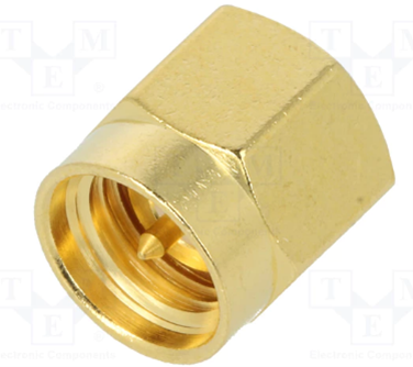
10x SMA quick connect adapters |
|
4x 50 Ohm terminators |
|
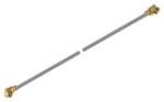
4x uFL cables |
|
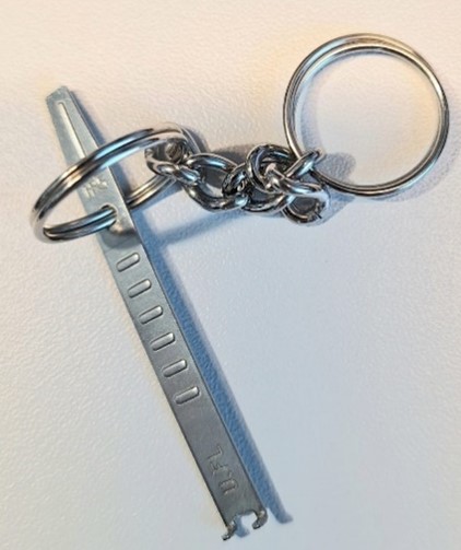
1x uFL cable remover key |
|
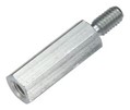
2x Spacers (12 mm) |
|
Additional DUT items (no image):
1x Portable Display + Power Supply
1x SATA III SSD
1x SATA to eSATA cable
1x USB 3 stick + USB Type C adapter
1x Micro USB cable
1x Test SD card for the DUT
1x BR-048139 Jupiter SDR Main Board (DUT)
1x GPIO loopback cable
1x Add-on Interface test board
2x RF loopback cables
1x Reference Clock cable
1x MCS cable
1x Jupiter USB Type C supply + USB Type C cable
Warning
uFL cables must always be replaced after testing a batch of 30 Add-on boards
Known good Main Board must always be replaced after testing a batch of ~900 tested Add-on boards
SMA quick connect adapters must be replaced after testing a batch of 500 DUTs or they could be replaced every time you start a new production LOT
Note
DUT is any of the following:
Main Board
RF Add-on Board
Assembled System
Note
The test setup needs to be connected to the internet during testing process to allow the test logs to be uploaded to the server.
To complete the test setup, you need to have 5 Power Outlets available:
2x Monitor supply
1x RPI supply
1x Ethernet Switch supply
1x DUT USB power supply
Required Software
The test image is provided on a pre-configured SD card.
Required Setup
Initial Setup
No. |
Steps |
|---|---|
1 |
Insert the SD card into the Raspberry Pi |
2 |
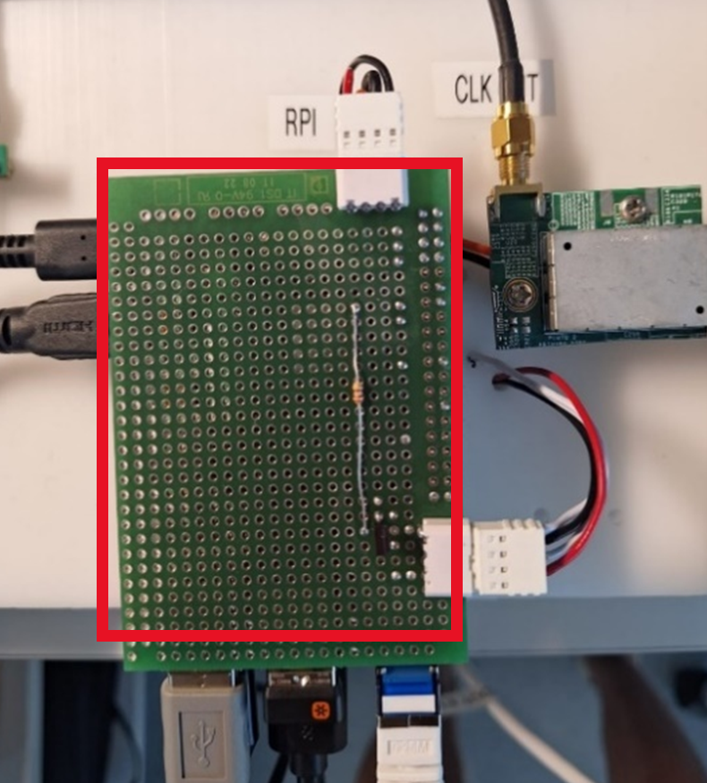
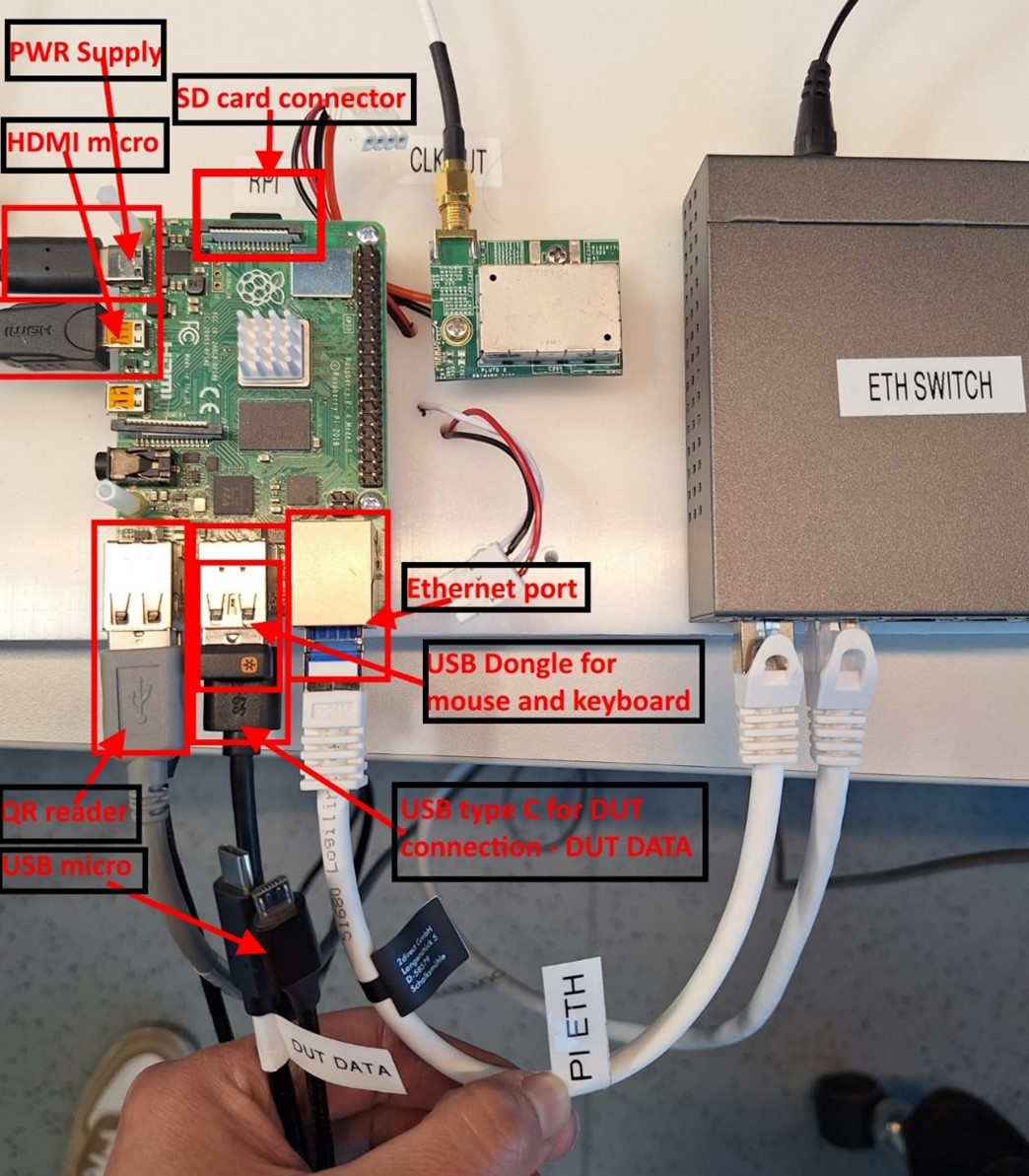
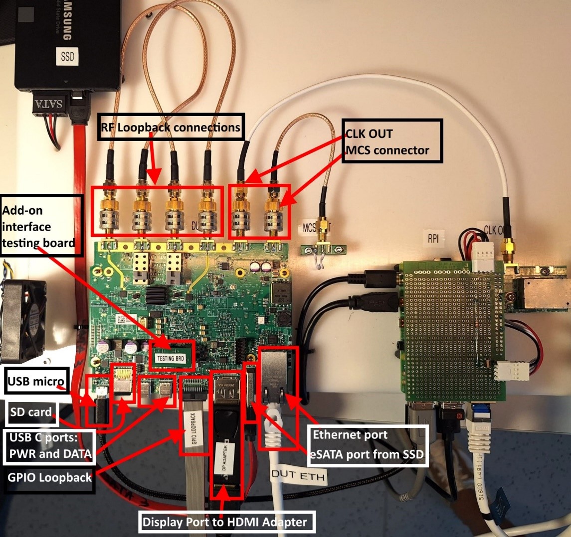
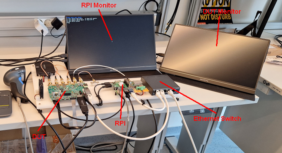
Make the following connections to the RPI:
|
3 |
Connect QR code reader to RPI’s USB port (labeled QR READER) OR During System test, instead of QR code reader, connect the Dymo LabelWriter 450 Turbo printer |
4 |
The RPI comes with the PWR shield connected |
5 |
Connect External Reference clock SMA cable and MCS SMA cable (CLK OUT and MCS OUT) |
6 |
Power up the Ethernet switch (label ETH PWR) |
7 |
Power up RPI - power supply to power outlet |
Labeling
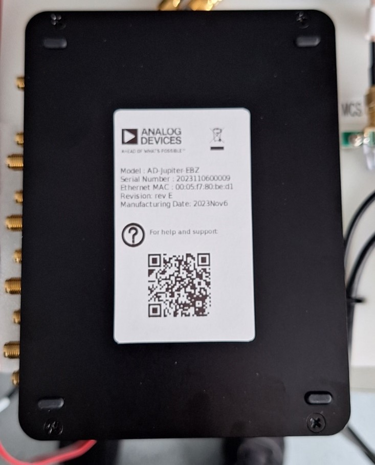
The label stuck on the boards will be scanned during testing and the information will be stored into the board’s EEPROM. Also, the test logs will contain the info on the labels so that we can track the logs.
The label stuck on the enclosure will allow us to identify the hardware our customer is referring to and we can always check the testing logs to check how the device was performing during testing.
Test Sequence 1 - Main Board Test
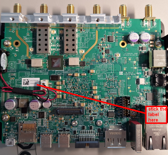
Main Board Labeling
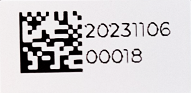
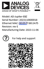
The label contains the board ID and its QR code:
Manufacturing Date in the format yyyymmdd
Board ID: a 5 digit decimal number
The label will be printed by the manufacturing company on their available printer. The label needs to be stuck to the PCB before production testing since it needs to be scanned during testing.
Label size: 13.81 x 6.35 mm
Example: 2023110600018
Main board label position |
|
Main board labeling example |
|
Main Board Test Setup
No. |
Steps |
|---|---|
1 |
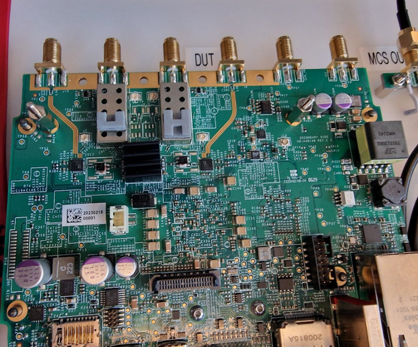
Place BR-048139 Jupiter SDR Main Board (DUT) into the fixture |
2 |
Insert the following cables into the DUT:
|
3 |
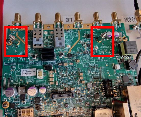
Connect External Reference clock cable and MCS cable (CLK OUT and MCS OUT) to SMA connectors of the DUT board |
4 |
Before testing another board, or at the work day end, make sure to remove all the cables from the DUT |
5 |
After disconnecting the DUT, place a new one and repeat testing steps 2 and 3 |
Placing DUT into the fixture |
|
DUT cable insertion |
|
External Reference clock SMA cable connection |
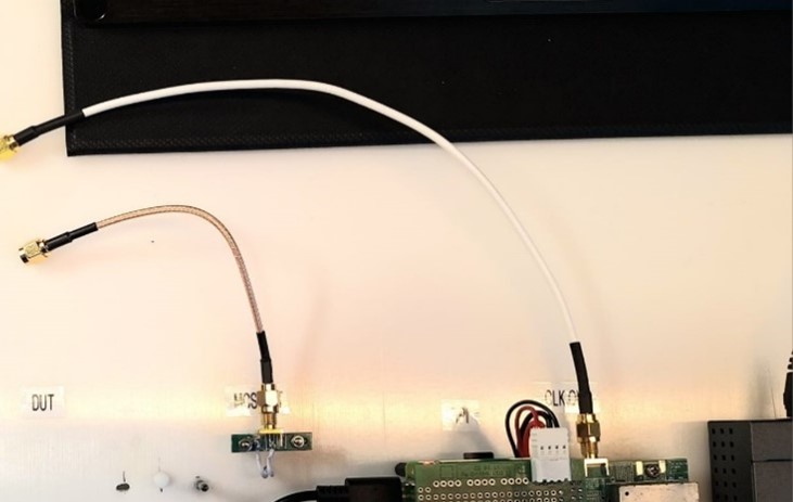
|
DUT cable removal |
|
Test Sequence 2 - Add-on Board Test
Add-on Board Labeling
The label will be identical with the one from the main board. The label needs to be stuck to the PCB before production testing since it needs to be scanned during testing.
Info: Manufacturing Date and Board ID
Example: 2023110600018
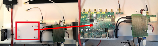
Add-on board label position |
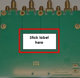
|
Add-on Board Test Setup
No. |
Steps |
|---|---|
1 |
Perform the steps from initial setup / make sure the initial setup is prepared |
2 |
Insert the SD card into the main board (known good) |
3 |
Known good main board and Add-on board (DUT) connections: Fix down the main board using 12 mm spacers |
4 |
Stick the QR code label to the add-on board |
5 |
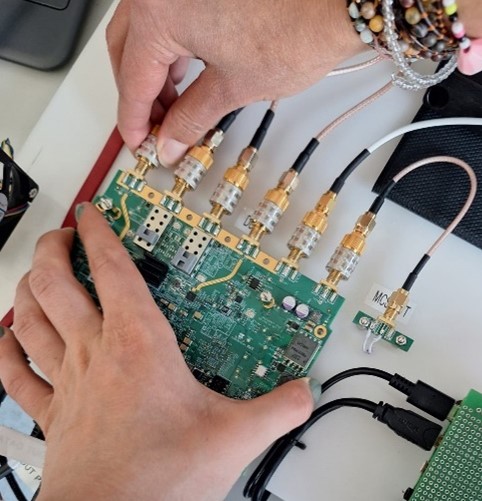
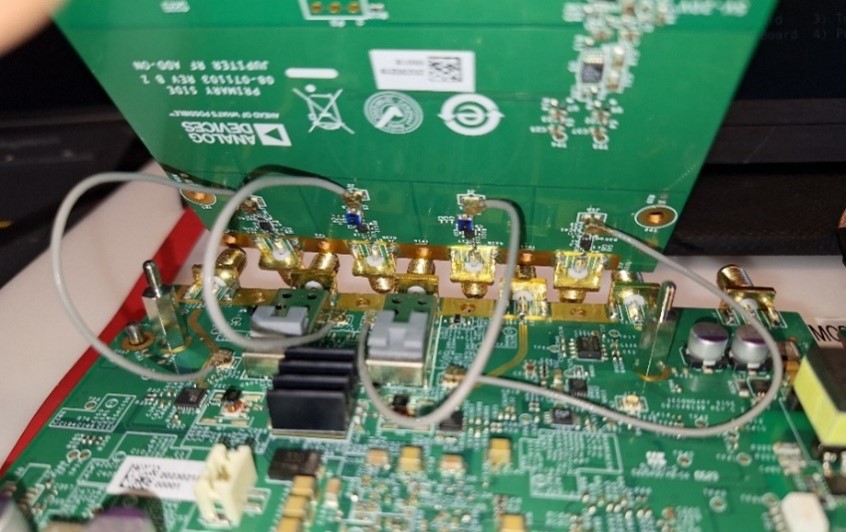
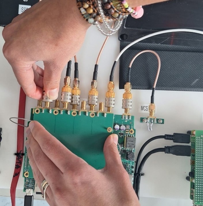
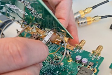
Connect uFL cables to the main board (known as good) |
6 |
Connect add-on board using uFL cables and add-on interface connector |
7 |
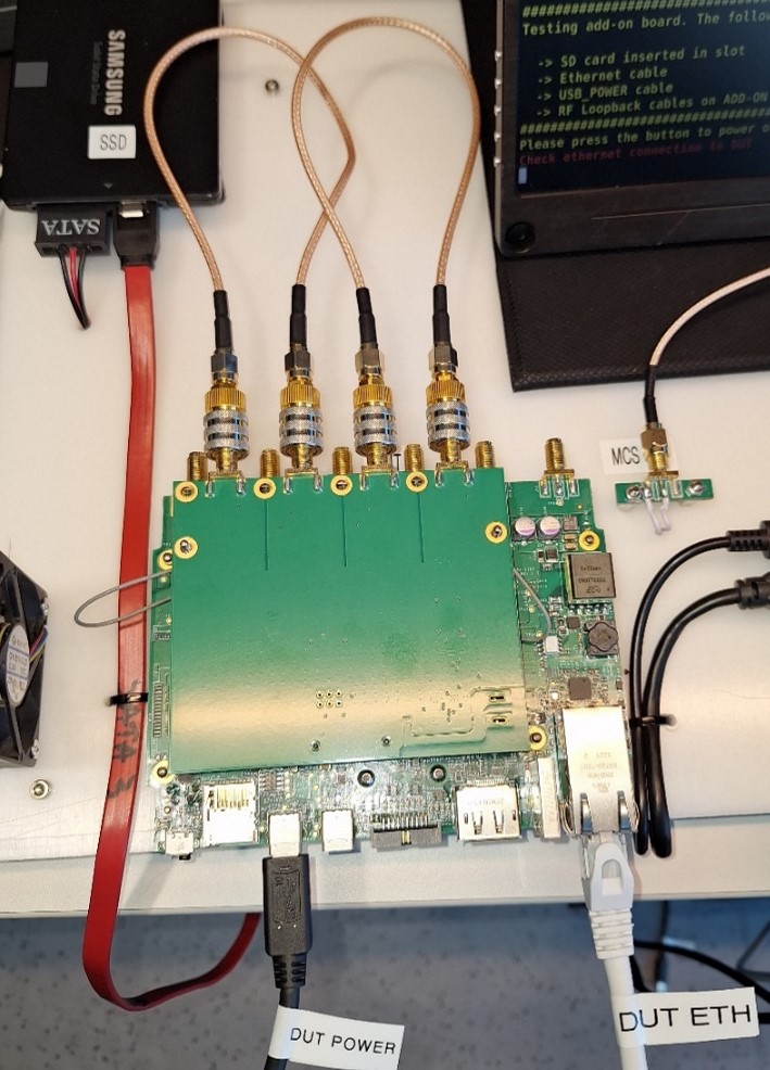
Connect the Ethernet cable coming from the Ethernet Switch (DUT ETH - 50cm) |
8 |
Connect the USB Type C power supply to USB_POWER port |
9 |
Press the Power button to power on the board. The LED should turn blue |
10 |
Wait for the test to finish. Make sure the power LED is RED, then:
|
11 |
Connect the next add-on board |
12 |
Repeat testing steps 4 to 10 |
Main board and add-on board connection |
|
DUT connections for add-on board test |
|
uFL cable connection to main board |
|
Add-on board connection |
|
RF loopback cable connection |
|
RF loopback cable (labeled B) |
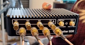
|
Power button press |
|
Unplug loopback cables |
|
Remove uFL cables using key |
|
Test Sequence 3 - System Test
Attention
When the system is assembled, make sure the Main Board and Add-on Board placed in the same enclosure have the same IDs.
System Labeling
The label will be printed by the testing application only if it PASSes the test.
Label size: 46 x 78 mm (Dymo 99016-2)
Printer: Dymo LabelWriter 450 Turbo
The System label has the following format shown below. Stick the label on the bottom of the enclosure.
Dymo LabelWriter 450 Turbo |

|
System label example |
|
System Test Setup
No. |
Steps |
|---|---|
1 |
Perform the steps from initial setup / make sure the initial setup is prepared |
2 |
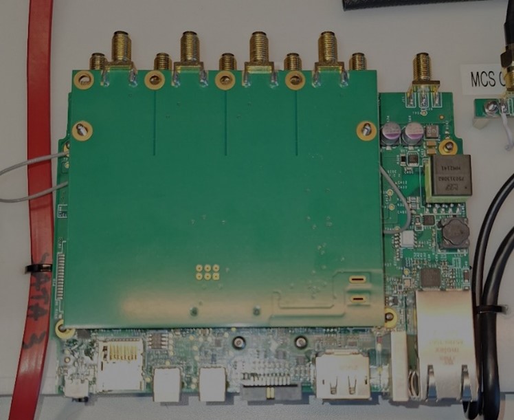
Place the support board along with protective foam on DUT place |
3 |
Insert the SD card into the SD Card Slot of the enclosure |
4 |
Connect RF loopback cables using SMA Quick connect adapters on the add-on board ports (labeled B) |
5 |
Connect the RF terminators on the MAIN BOARD ports using quick connect (labeled A) |
6 |
Connect the Ethernet cable coming from the Ethernet Switch (DUT ETH - 50cm) |
7 |
Press the Power button to power on the board. The LED should turn blue, press Enter |
8 |
Wait for the test to finish |
9 |
Unplug the loopback cables and terminators. Unplug ETH cable |
10 |
Connect another DUT and perform testing steps 3-8 |
Support board with protective foam |
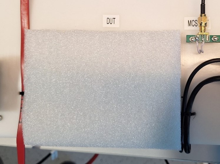
|
SD card slot on enclosure |
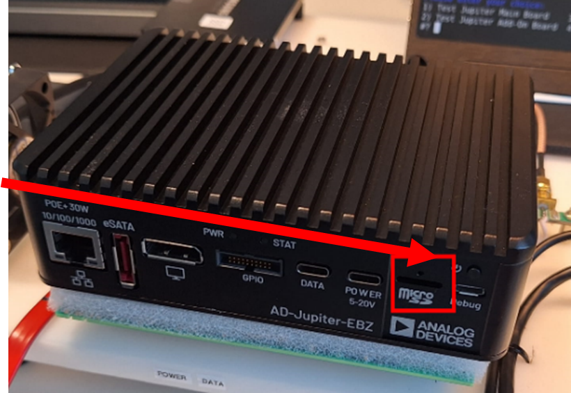
|
Power button press for system test |
|
Test Process
Running the Test Software
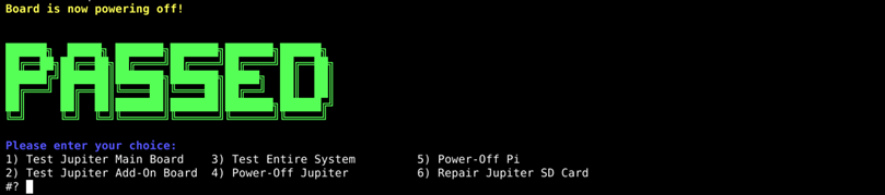
After the Raspberry Pi boots up, the test screen will appear on the monitor as shown below.
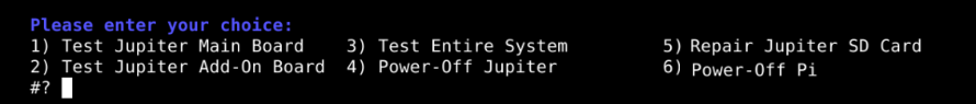
The following test menu should appear:
Please enter your choice:
1) TEST MAIN BOARD
2) Add-ON test
3) System Test
4) Power-Off Pi
5) Repair SD card
1) Test Main Board
Type “1” into the terminal then press ENTER to start 1) TEST MAIN BOARD.
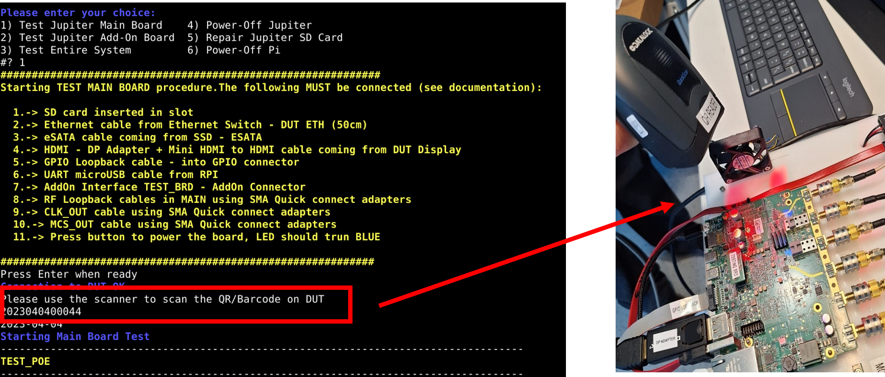
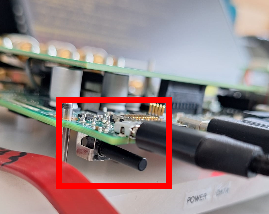
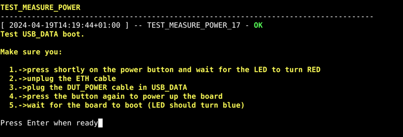
Test USB_DATA boot:
During this test, perform the following:
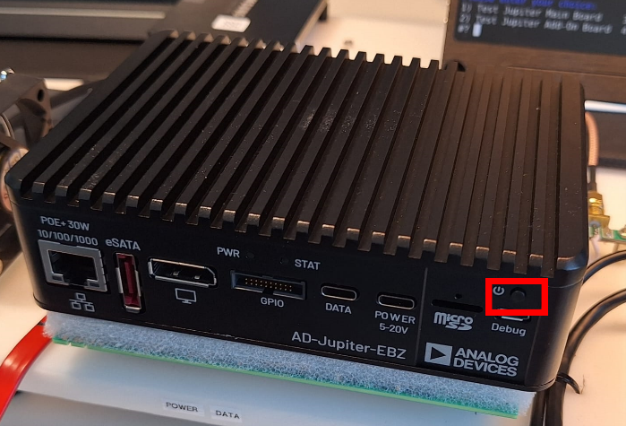
Press shortly on the power button and wait for the LED to turn RED
Unplug the ETH cable (DUT ETH)
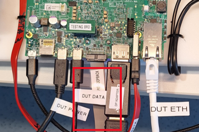
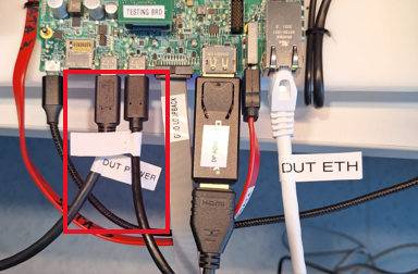
Plug the USB-C power cable in USB_DATA port of the DUT
Power cable connection to DUT |
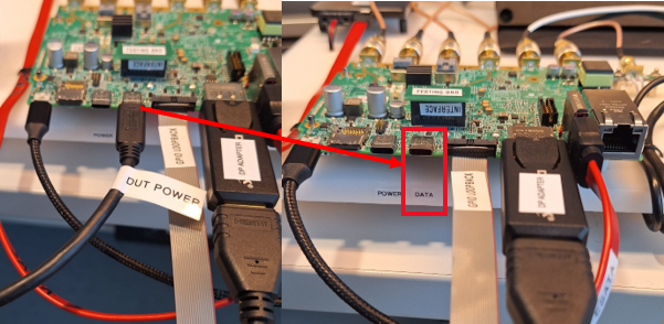
|
USB-C connection to USB_DATA port |
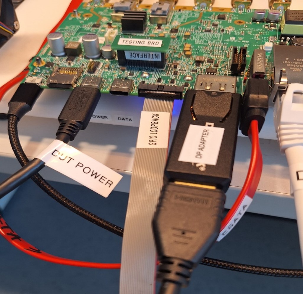
|
Press the button again to power up the board
Wait for the board to boot (LED should turn blue); it will take about 30 seconds to fully boot the board
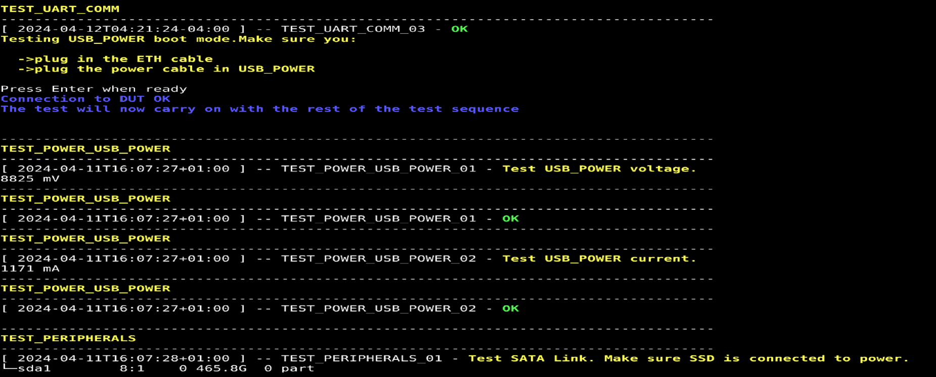
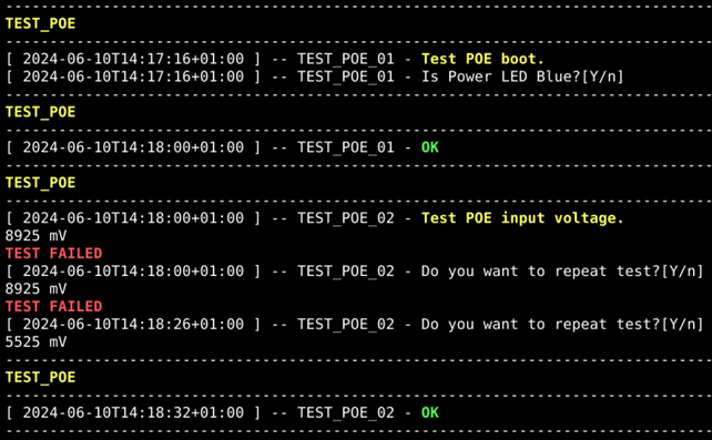
Test USB_POWER boot:
During this test, perform the following:
Plug in the DUT ETH cable
Plug the USB-C power cable in USB_POWER port of the DUT
USB_DATA port testing - Host mode:
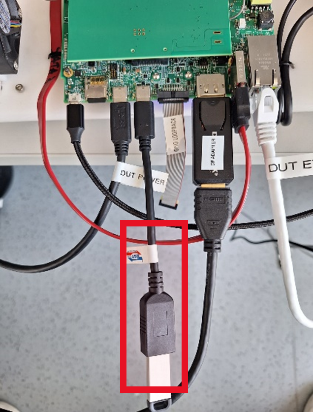
Plug OTG cable with a connected USB3 flash device (OTG cable labeled USB DONGLE) in the DATA USB C port.
OTG cable connection |
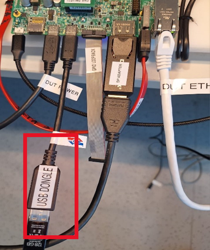
|
Host mode test |
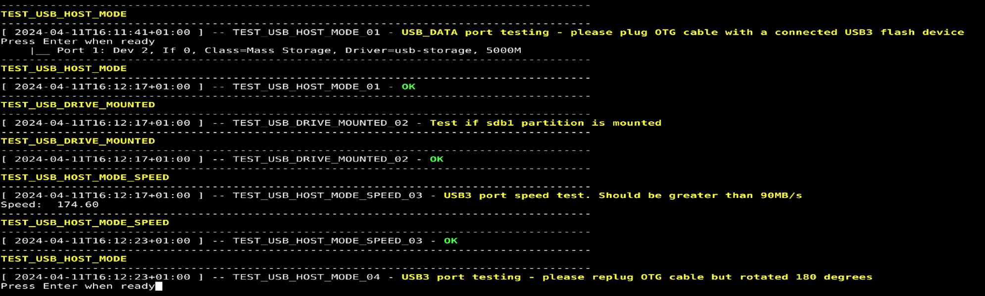
|
Replug OTG cable but rotated 180 degrees:
USB_DATA port testing - Device mode:
Plug in USB_DATA Type C cable between Pi and DUT:
Replug cable but rotated 180 degrees:
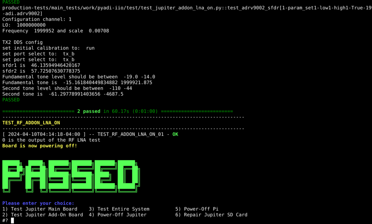
After the test suite passed, a green “PASSED” message will appear on the screen.
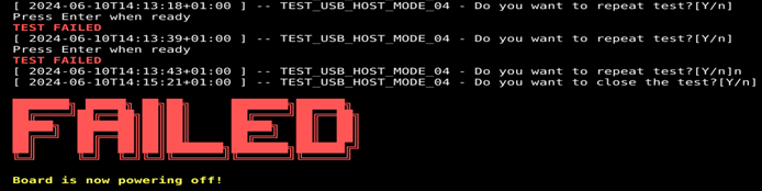
When at least one test is failing, at the end of the test suite a “FAILED” message will be displayed.
Note
In case a failure occurred, a “FAILED” message will be displayed and you will be prompted to enter a new command.
If at any point a test fails, you are prompted with a message saying: “Do you want to repeat test?”. In case the test failed due to an unconnected cable, or some exceptional reason, you can opt to repeat the last test as shown below:
Alternatively, if you realize that there is something wrong with the board and you do not wish to continue with the rest of the procedure, you can press “n” + “ENTER” and stop the test, which will also prompt a test failure:
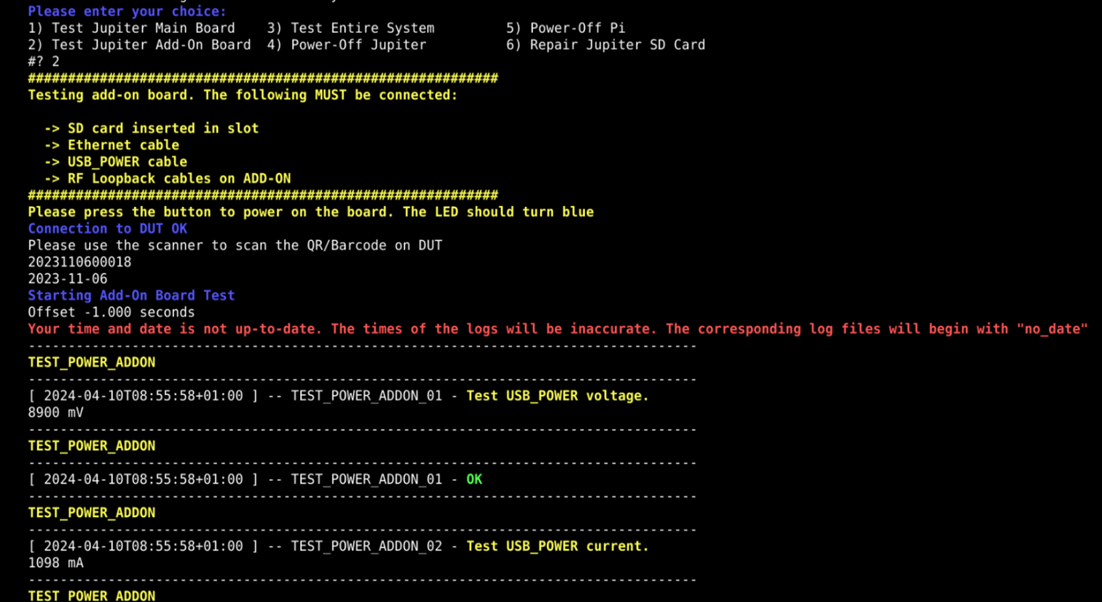
2) Add-on Test
Type “2” into the terminal and press ENTER to start 2) Add-ON test.
In case a failure occurred, a “FAILED” message will be displayed.
After the test is passed, a green “PASSED” message will appear on the screen.
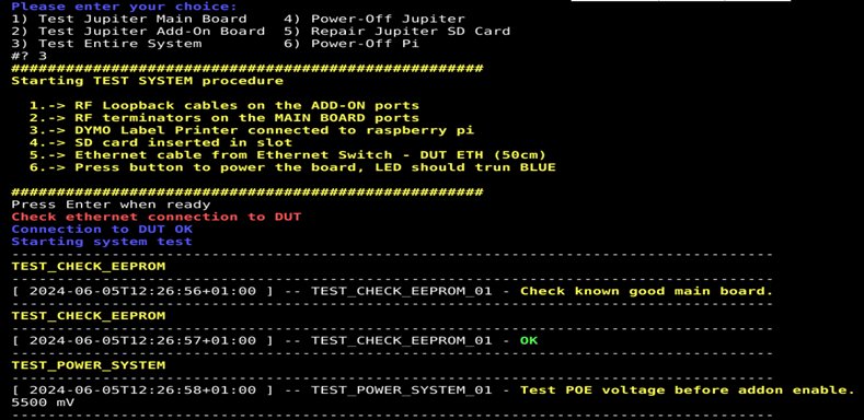
3) System Test
Type “3” and press ENTER to start 3) System Test.
Make sure:
SD card inserted in slot
Ethernet cable connected
RF Loopback cables on the ADD-ON ports
RF terminators on the MAIN BOARD ports
Dymo Label printer is inserted into Raspberry Pi USB port (instead of QR code reader)
Press ENTER to continue.
After the system test PASSes, a QR code label will be printed and should be stuck on the bottom of the enclosure.
Test Status LED:
Is Status LED blinking?
Pass Criteria
Main boards test: Test 1) has successfully passed
Add-on boards: Test 2) has successfully passed
System: Test 3) has successfully passed
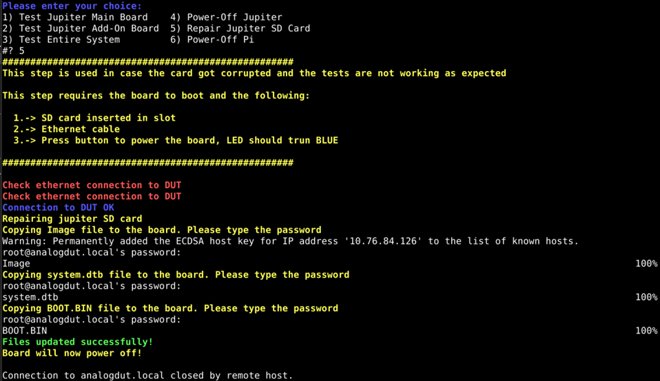
5) Repair SD Card
Note
In the unlikely case the board is not behaving as expected, run the
5) Repair SD card option in order to repair the boot image. Please be
aware that you will be required to input the password analog three times
during the repair steps.
4) Power-Off Pi
When you are done testing, press “4” and press ENTER to power-off the Raspberry Pi.