Temperature Controller Application
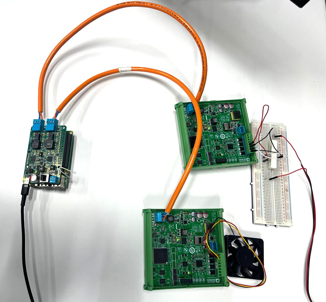
This sample application demonstrates a basic Temperature Controller using the AD-RPI-T1LPSE-SL board, two AD-SWIOT1L-SL boards, a Raspberry Pi, a fan actuator and a temperature sensor. The system reads temperature data and adjusts fan speed (via SWIOT1L output) based on configurable thresholds and hysteresis.
Prerequisites
Python 3.8 or newer (3.8–3.11 tested with pyadi-iio). Ensure that a compatible version is installed on your system before continuing. Older versions (<3.8) may not work reliably with pyadi-iio.
Git command-line tools installed.
Raspberry Pi with Kuiper 2 image installed. Follow the instructions in the ADI Kuiper Linux documentation to prepare the Raspberry Pi.
Ensure that the first two Software Setup steps described in Software Setup (Downloading and Flashing the Micro-SD Card and Configuring the Micro-SD Card) are performed with the Kuiper 2 image, not with previous Kuiper releases. These steps must be redone after flashing Kuiper 2 to ensure proper compatibility before continuing.
Hardware Setup
Equipment Needed
1x AD-RPI-T1LPSE-SL Board
2x AD-SWIOT1L-SL Boards
1x Raspberry Pi 4 Model B running Kuiper 2
1x TMP01 Temperature Sensor
1x MC002103 DC Axial Fan
1x Raspberry Pi USB Type-C Power Supply (5V, 3A)
1x Power Resistor (6.2Ω, 10W was used by us)
1x Power Supply for the Power Resistor (5V, 1A was used by us)
Setup Procedure
Connect the AD-RPI-T1LPSE-SL board to the Raspberry Pi via the 40-pin header
Connect the two AD-SWIOT1L-SL boards to the AD-RPI-T1LPSE-SL board via the T1L connectors
Connect the TMP01 temperature sensor to the first AD-SWIOT1L-SL board
The first SWIOT1L-SL board is used to both power the TMP01 sensor and measure its analog output voltage (VPTAT), which encodes the temperature.
Channel 3 (CH3) is configured as a Voltage Output and provides the sensor supply voltage. Connect:
CH3 SWIO→TMP01 V+CH3 GND→TMP01 GND
Channel 4 (CH4) is configured as a Voltage Input to measure the TMP01 analog output. Connect:
CH4 SWIO→TMP01 VOUTCH4 GND→TMP01 GND
Note
CH3 provides a regulated 5 V supply to power the TMP01, while CH4 is configured as a high-impedance voltage input with a 0–5 V range to measure the TMP01 VOUT signal. Both channels must share the same ground reference with the sensor.
Power on the power resistor. Attach the power resistor to the TMP01 sensor to simulate temperature changes via rubber bands or similar means to dissipate heat. The power resistor acts as a heat source simulating a GPU under load (similar to running a graphics-intensive application like SuperTuxKart).
Connect the fan actuator to the second AD-SWIOT1L-SL board
The second SWIOT1L-SL board drives the fan according to the control loop.
The fan is powered directly from channel 0, configured as a Voltage Output:
CH0 SWIO→Fan +CH0 GND→Fan −
Connect the tachometer output to channel 1 to monitor fan speed (optional):
CH1 SWIO→Fan Tach Out
Power the Raspberry Pi with a 5V, 3A USB Type-C power supply.
Software Setup
Repository Cloning
Clone the repository and checkout the swiot branch:
analog@analog:~$
git clone https://github.com/analogdevicesinc/pyadi-iio.git
analog@analog:~$
cd pyadi-iio
analog@analog:~/pyadi-iio$
git checkout swiot
Install Python dependencies:
analog@analog:~$
python3 -m venv ./venv
analog@analog:~$
source venv/bin/activate
analog@analog:~$
pip install -e .
analog@analog:~$
pip install matplotlib
Firmware Flashing
Each AD-SWIOT1L-SL must be updated with the provided firmware image.
Follow the official update instructions here: Updating the AD-SWIOT1L-SL firmware.
Repeat the process for both boards.
Use the firmware images provided below. These images configure the boards with static IP addresses:
The first board will have the
192.168.97.40IP addressThe second board will have the
192.168.97.41IP address
Four different firmware images are provided. We recommend using the ones mentioned above. You may use the other two images if you wish to change the IP addresses of the boards or to extend the application.
Applying Overlays
Overlays are required to enable the proper device tree configurations for the AD-RPI-T1LPSE-SL HAT.
Open a terminal and write this command:
analog@analog:~$sudo tee -a /boot/config.txt <<'EOF'dtoverlay=rpi-t1lpse-apl dtoverlay=rpi-t1lpse-class12 EOF
Network Setup
The Raspberry Pi has two Ethernet interfaces connected to the two AD-SWIOT1L-SL boards. We will create two persistent NetworkManager connections with autoconnect enabled for each interface in order to communicate with the boards:
eth1will use192.168.97.30/32and route to the SWIOT1L board at192.168.97.41eth2will use192.168.97.31/32and route to the SWIOT1L board at192.168.97.40
Open the terminal and run the following commands.
Add the wired connection interfaces:
analog@analog:~$
sudo nmcli connection add \
   type ethernet \
   ifname eth1 \
   con-name "Wired connection 2" \
   ipv4.method manual \
   ipv4.addresses 192.168.97.30/32 \
   ipv4.routes "192.168.97.41/32" \
   ipv6.method disabled \
   connection.autoconnect yes
analog@analog:~$
sudo nmcli connection add \
   type ethernet \
   ifname eth2 \
   con-name "Wired connection 3" \
   ipv4.method manual \
   ipv4.addresses 192.168.97.31/32 \
   ipv4.routes "192.168.97.40/32" \
   ipv6.method disabled \
   connection.autoconnect yes
Activate the new connections:
analog@analog:~$
sudo nmcli connection up "Wired connection 2"
analog@analog:~$
sudo nmcli connection up "Wired connection 3"
Reboot the Raspberry Pi to ensure autoconnect is applied:
analog@analog:~$
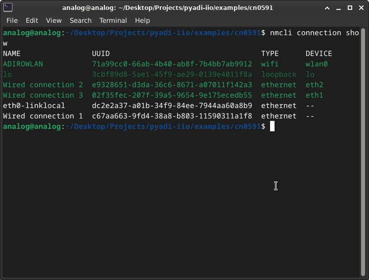
sudo rebootVerify that the new connections are active:
analog@analog:~$
nmcli connection show
Verify routing and connectivity to the boards:
analog@analog:~$
ip routeanalog@analog:~$
ping 192.168.97.40
analog@analog:~$
ping 192.168.97.41
Application Execution
When executed, the demo continuously reads temperature from the external TMP01 and applies a simple thermostat hysteresis:
Fan turns ON when temperature is ≥ TEMP_ON
Fan turns OFF when temperature is ≤ TEMP_OFF
Between thresholds, the fan keeps its previous state
The thresholds are configured via command-line arguments (see below). The
application validates that TEMP_OFF < TEMP_ON; otherwise it exits with an error.
The on-board ADT75 is included as a secondary reference measurement to provide a quick sanity check that the SWIOT1L-SL is operational and to indicate local ambient/board temperature.
During runtime, the application prints sensor readings and fan state in the console, and displays two plots:
Temperature vs Time — external TMP01 temperature and the on-board ADT75 temperature from the SWIOT1L-SL “temperature sensor board”, with ON/OFF thresholds.
Fan State vs Time — graphical representation of when the fan is active.
Command-line arguments
The demo accepts optional command-line arguments to select the IP addresses for each SWIOT1L-SL board and to configure the thermostat thresholds:
--temp-ip: IP address of the SWIOT1L-SL board that powers/reads the TMP01 and provides the ADT75 reference trace (default:192.168.97.41)--fan-ip: IP address of the SWIOT1L-SL board that drives the fan (default:192.168.97.40)--temp-on: temperature in °C at/above which the fan turns ON--temp-off: temperature in °C at/below which the fan turns OFF
Note
--temp-off must be strictly less than --temp-on (hysteresis condition).
Running the Application
Run the Temperature Controller example with example thresholds:
analog@analog:~$
cd examples/rpi_t1lpse
analog@analog:~/examples/rpi_t1lpse$
python3 temperature_controller.py --temp-on 50 --temp-off 40
Specify board IP addresses and thresholds:
analog@analog:~$
python3 temperature_controller.py \
   --temp-ip 192.168.97.41 \
   --fan-ip 192.168.97.40 \
   --temp-on 50 \
   --temp-off 40
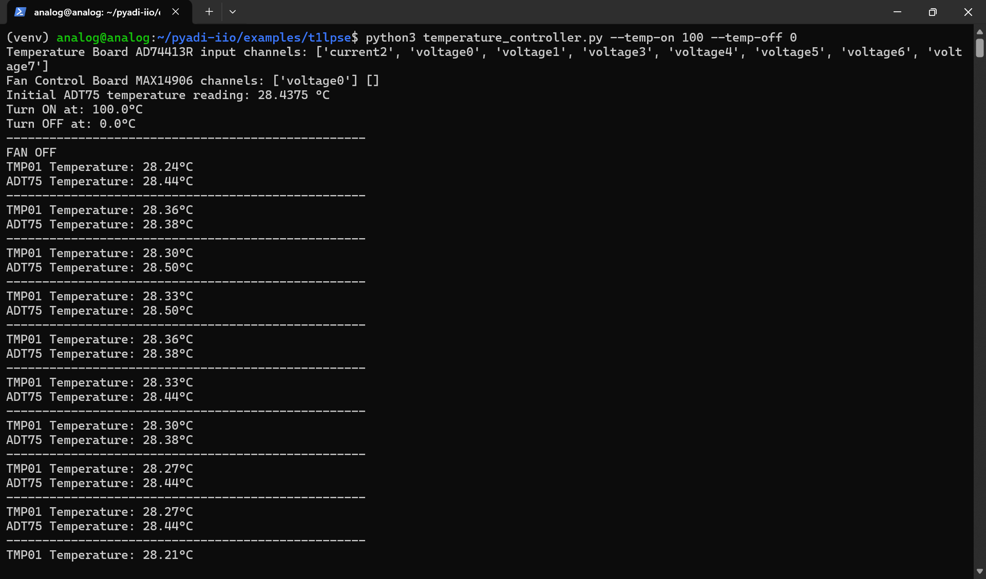
Figure 3 Example Console Output of the Temperature Controller Application
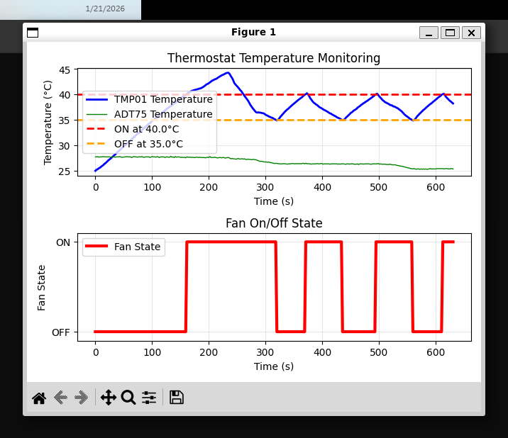
Figure 4 Example Plot Result of the Temperature Controller Application
System characterization
After running the application, the resulting temperature and fan state plots can be used to characterize the thermal behavior of the system.
Based on this characterization, appropriate thermostat thresholds may be chosen and applied either as defaults or via command-line arguments.
Wide thresholds (for example, fan ON at 100 °C and OFF at 0 °C) may be used during initial bring-up or validation, while tighter thresholds can be selected for normal operation.
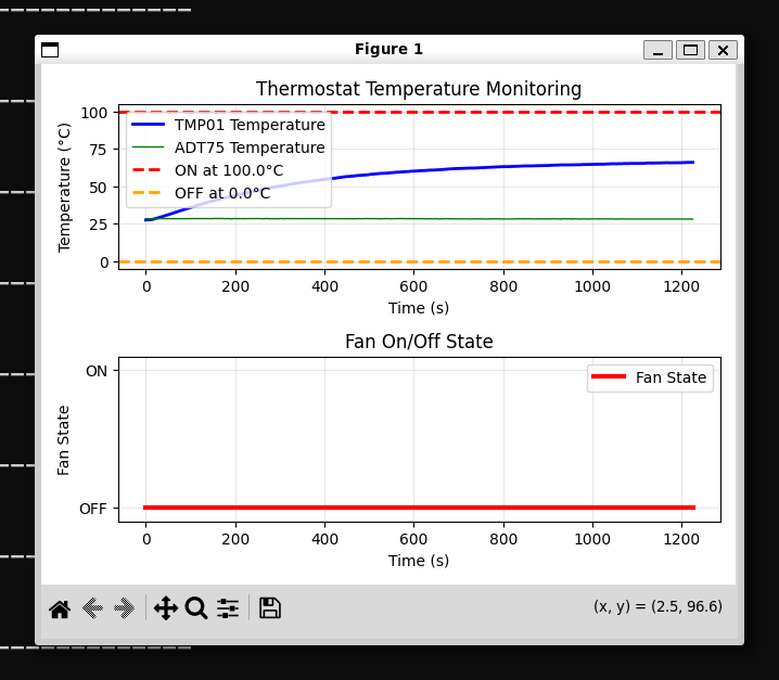
Figure 5 Temperature response and fan state during system characterization
Use Cases
This demo illustrates how the AD-RPI-T1LPSE-SL platform together with AD-SWIOT1L-SL boards can be applied in:
Thermal management - automatically controlling fans in enclosures or test setups
Process monitoring - maintaining temperature ranges in small-scale industrial or lab equipment
Educational examples - demonstrating closed-loop control