Production Testing
Overview
This document describes the production test procedure for the ADMV96S-WGBE-EK1 multi board kit. The procedure focuses on firmware programming and testing the two BR-073235 boards included in the kit.
Pre-Required Setup
Board Assembly
The disassembled boards must be assembled as a DUT (Device Under Test) before proceeding with the testing steps.
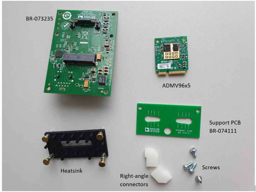
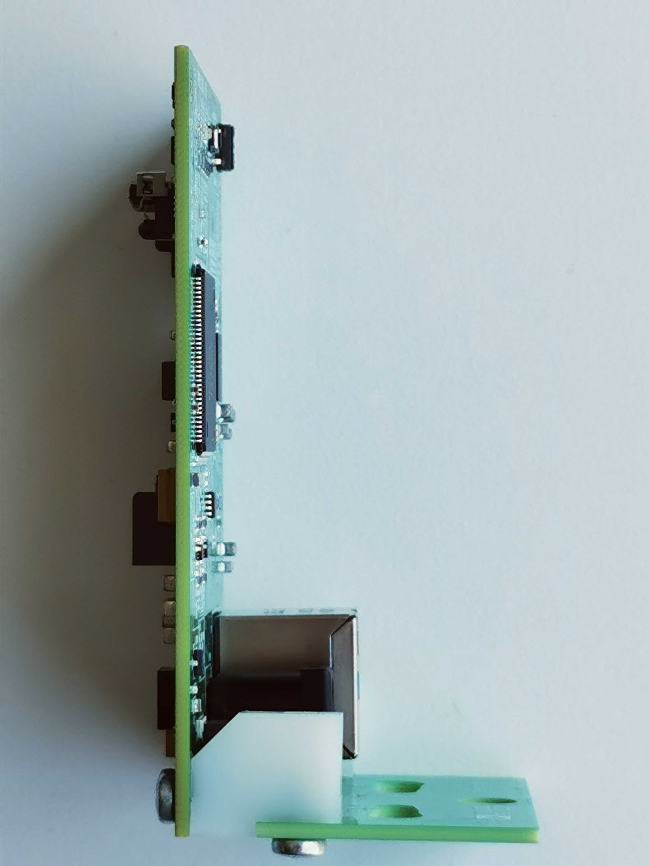
Attach the right-angle connectors with the screws to the support PCB and the BR-073235.
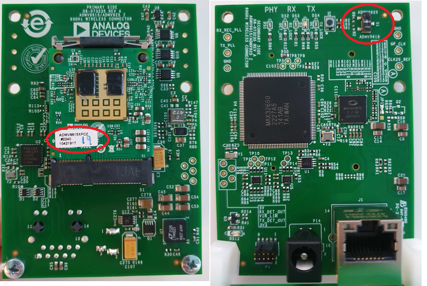
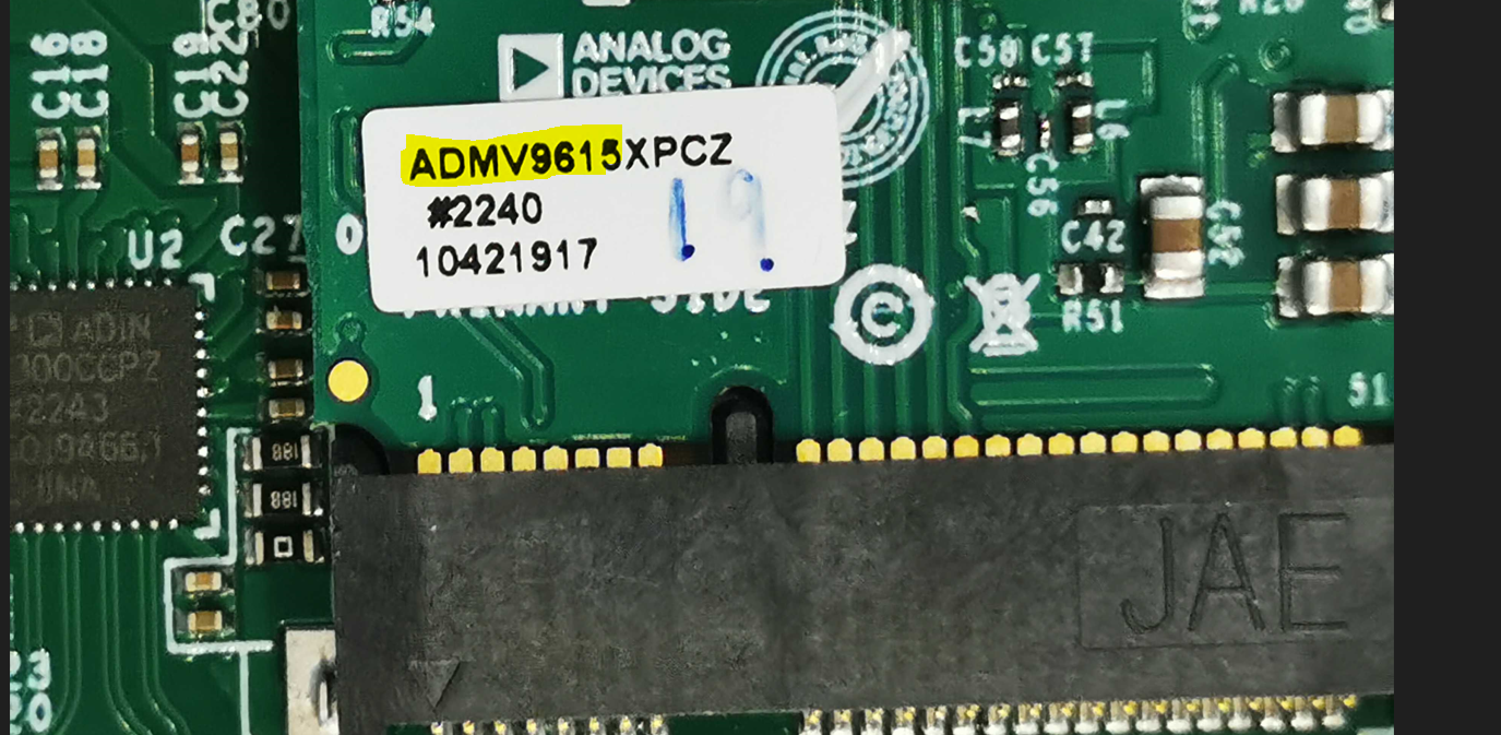
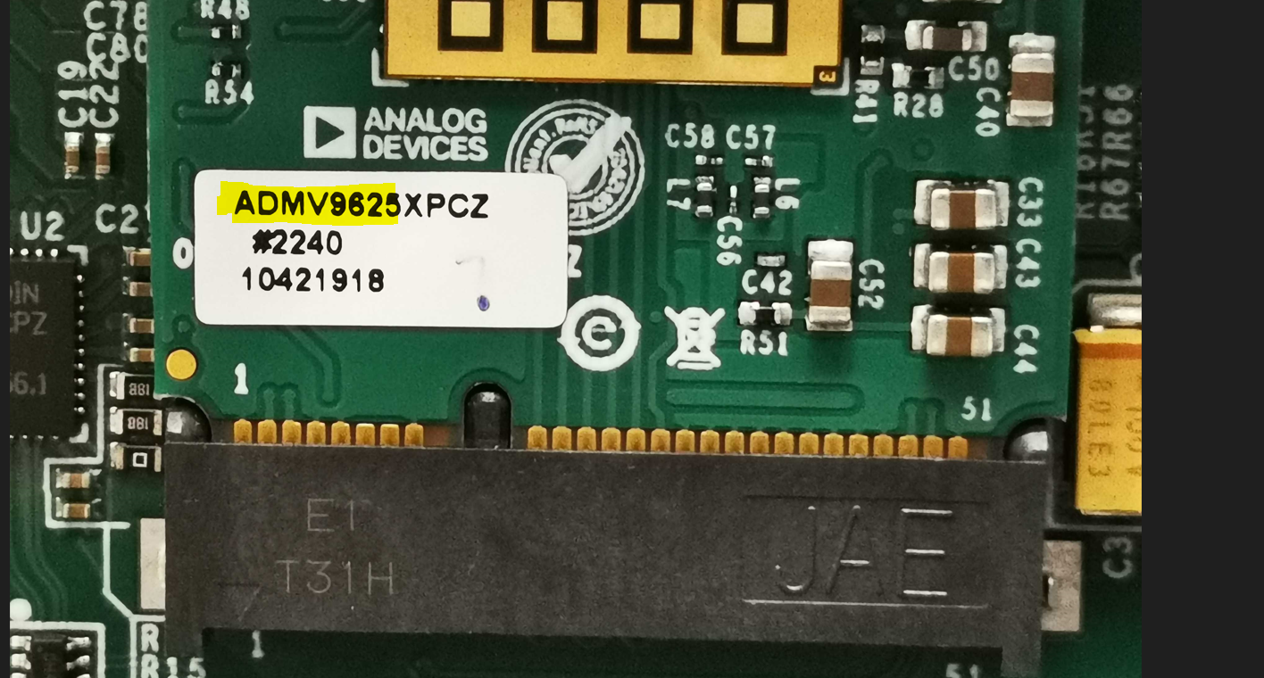
Populate the ADMV96x5 module on the board and read the label to identify whether it is an ADMV9615 or ADMV9625.
ADMV9615 Label
ADMV9625 Label
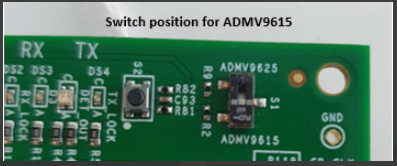
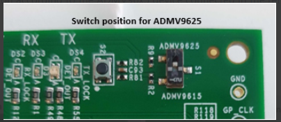
With a small tool like a screwdriver, move the S1 switch into ADMV9615 or ADMV9625 position depending on which module was installed.
ADMV9615 Switch Position
ADMV9625 Switch Position
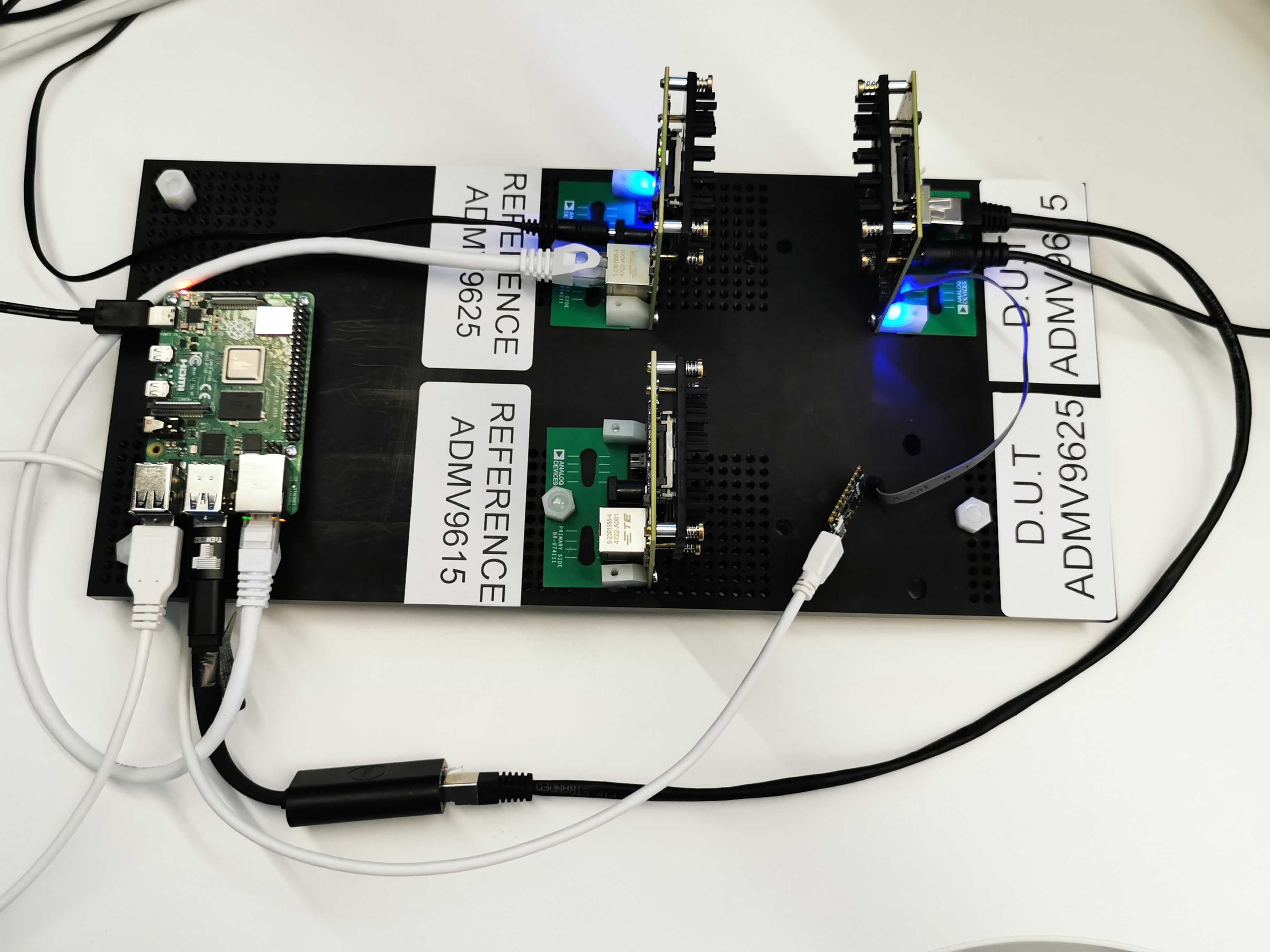
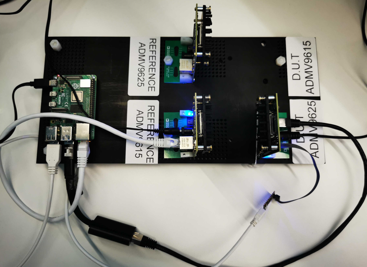
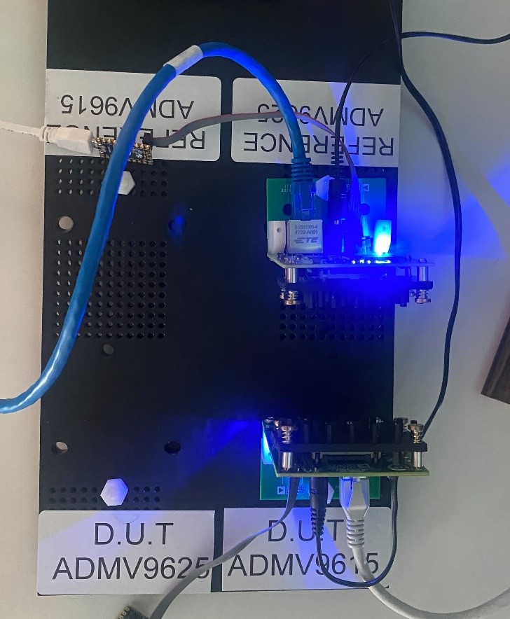
Mount the board on the test-jig in the correct position:
If the newly assembled board has an ADMV9615 module, mount it in front of the REFERENCE ADMV9625.
If the newly assembled board has an ADMV9625 module, mount it in front of the REFERENCE ADMV9615.
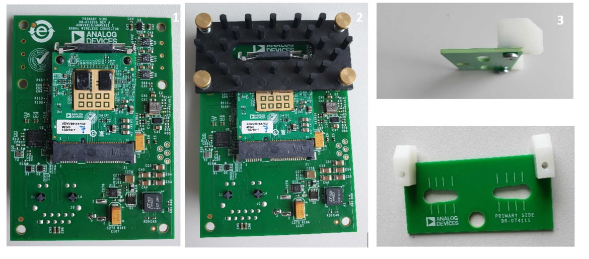
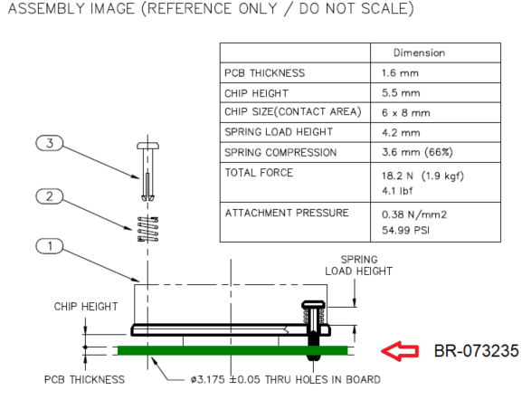
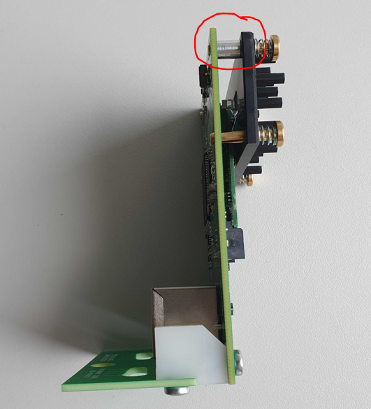
Heatsink Assembly
Mount a heatsink (S08ERQ0J-D) on each BR-073235 before packaging.
Steps for assembling the heatsink:
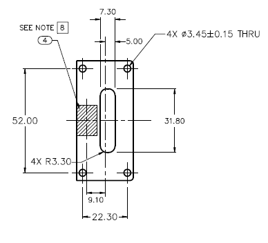
Make sure the S08ERQ0J-D heatsink has the thermal pad in the approximate position shown in the datasheet.
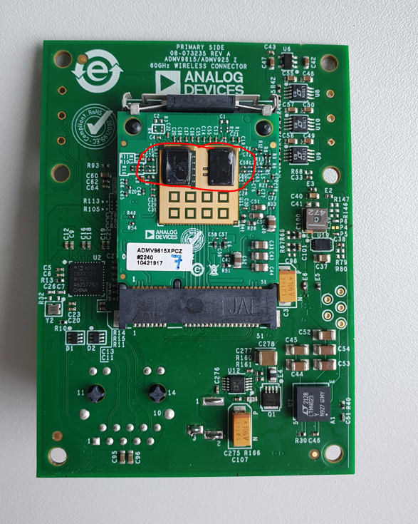
Peel the liner from the thermal pad and make sure it sticks to the highlighted area of the board.
Two aluminum unthreaded spacers (94669A101) must be placed between the BR-073235 and heatsink on the pins that go in the corners of the board.
Test Process
Required Hardware
Raspberry Pi 4
Mouse and keyboard
Ethernet to Usb3 adapter
MAX32625PICO (Daplink programmer) x2
Ethernet cable
Raspberry Pi power supply
Raspberry Pi HDMI cable
Display
2 Power supplies for the ADMV96S-WGBE
2 Reference ADMVs mounted to a support
Required Software
SD card with the test image.
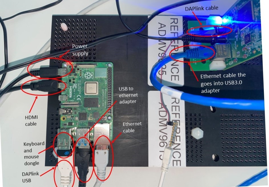
Required Setup
Insert the SD card into the Raspberry Pi.
Connect an Ethernet cable from the Pi Ethernet port to the D.U.T Ethernet port.
Connect an Ethernet cable to the reference ADMV and via an Ethernet to Usb3 adapter, connect it to the Pi Usb3.0 hub.
Connect the Daplink cable to the Raspberry Pi Usb on one side and to the JTAG SWD connector of the D.U.T. on the other side.
Connect the HDMI cable to the Pi and a Display.
Connect the keyboard and mouse dongle into the Raspberry Pi.
Connect the Raspberry Pi power adapter.
Power the DUT and the reference ADMV.
Testing Procedure
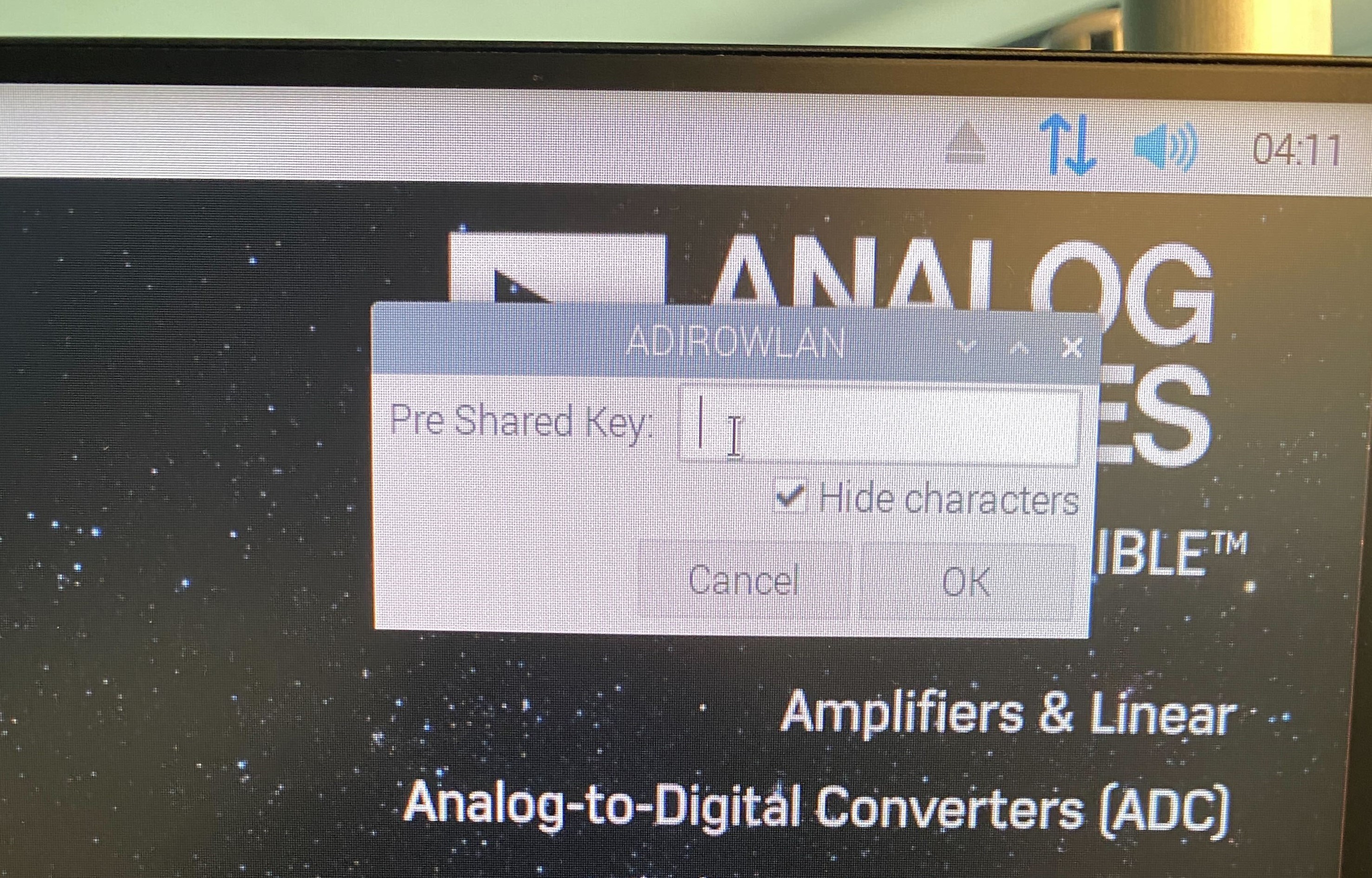
Wi-Fi Setup
Make sure the Raspberry Pi is connected to Wi-Fi before starting the tests.
Power the Raspberry Pi.
Press CONTROL+C to exit the test screen.
Click on the network and type in the password.
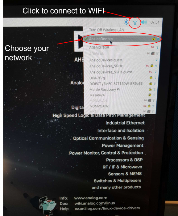
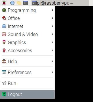
Reboot the Raspberry Pi to reinitialize the test screen by following the screen instructions.
Running the Tests
After rebooting the Raspberry Pi, the test screen will appear. Make sure the DUT and the reference board are perfectly parallel, facing each other.
1) Provisioning Test
Type 1 from the keyboard to start the Provisioning test.

The test has two parts: writing the firmware and checking that it is the “Production firmware”, and writing attributes.
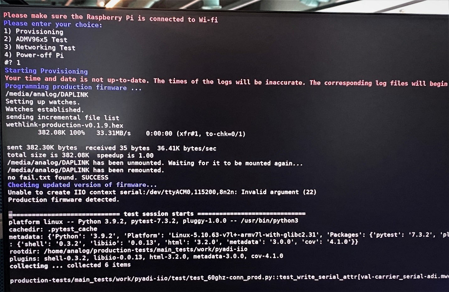
If the test is successful, a PASSED message will appear.
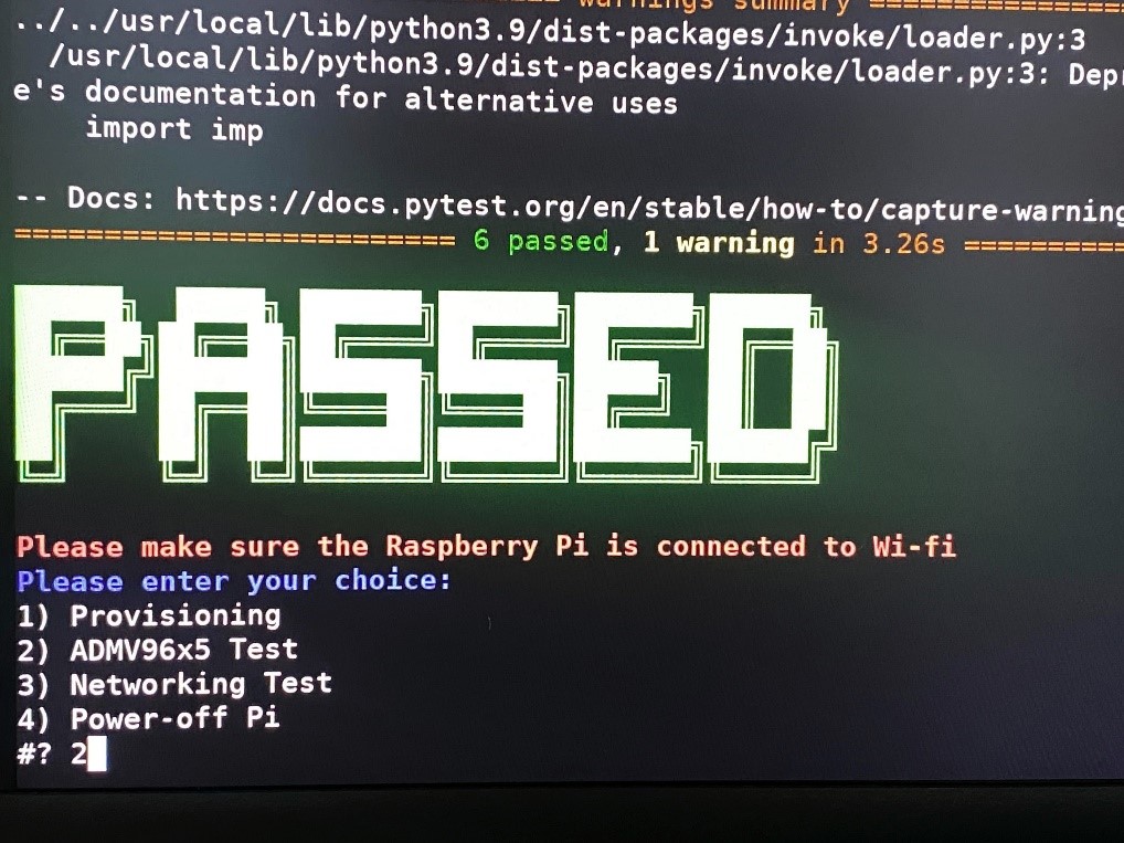
2) ADMV96x5 Test
Type 2 to run the ADMV96x5 Test.

If the test is successful, the PASSED message will appear.

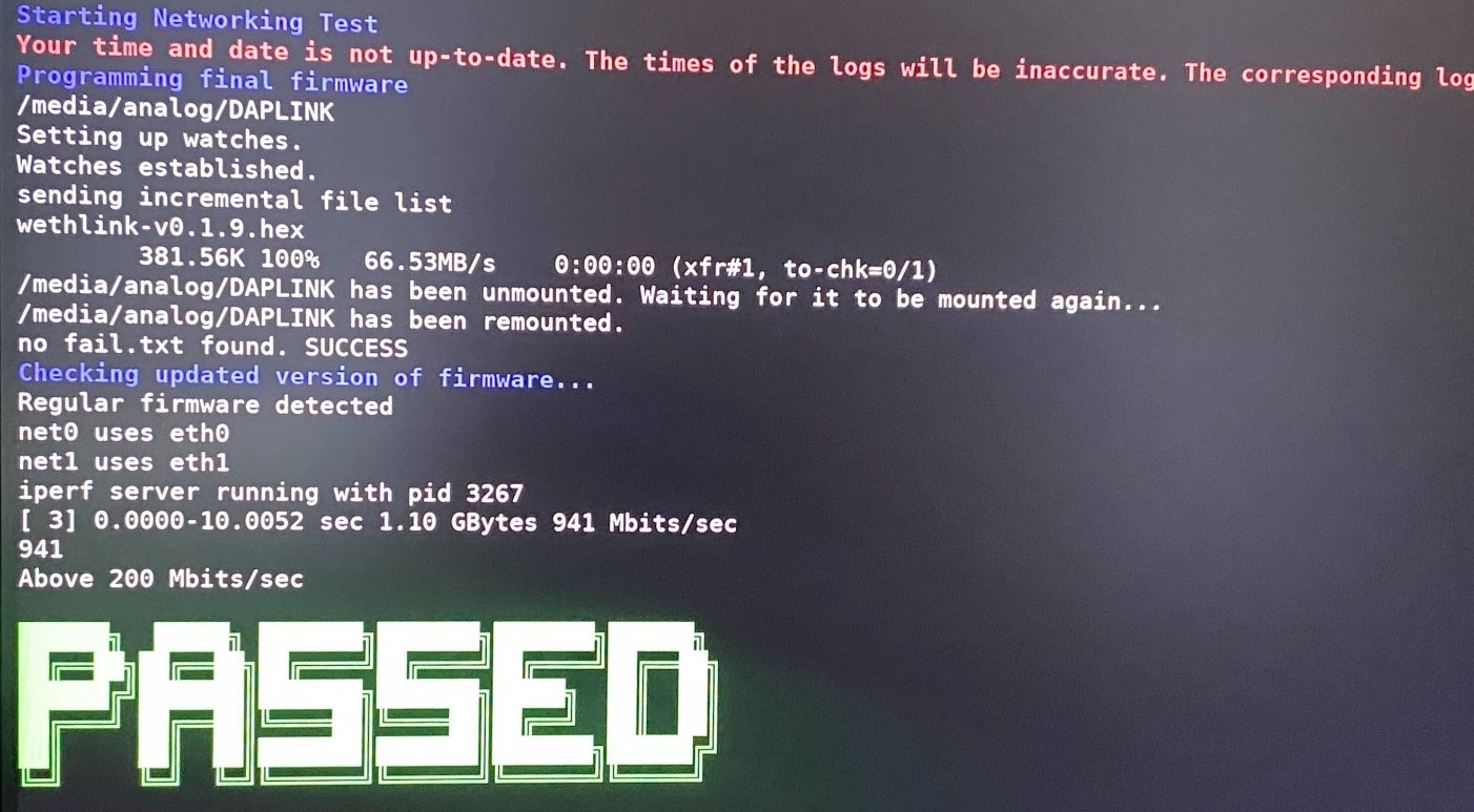
3) Network Test
Type 3 to run the Network Test.

If the test is successful, the PASSED message will appear.
Attention
If the networking test fails, unplug and plug again the Usb3 to Ethernet adapter into the Raspberry Pi.
After all tests are completed, proceed to the next untested DUT and repeat the testing procedure.
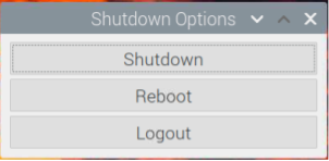
When done testing, type 4 to power off the Raspberry Pi.