Production Testing
Overview
The purpose of the test procedure is to identify connectivity issues, poor soldering, and potential manufacturing defects. Some of the issues are directly identified by explicit part-targeted tests, others are implicit, by running adjacent tests.
Test Duration
Step Description |
Estimate Time (minutes) |
|---|---|
Test bench setup |
3 min |
Software test |
5 min |
Total time |
8 min |
Test Requirements
Required Hardware
Raspberry Pi 4
HDMI cable
Mouse and keyboard
1 x AD-RPI-T1LPSE-SL board
1 x AD-APARD32690-SPOE (Device Under Test)
1 x AD-APARD32690-SL board
1 x T1L cable
12V power supply USB Type-C
MAX32625PICO (DAPLink programmer)
Required Software
The test image is provided on a pre-configured SD card.
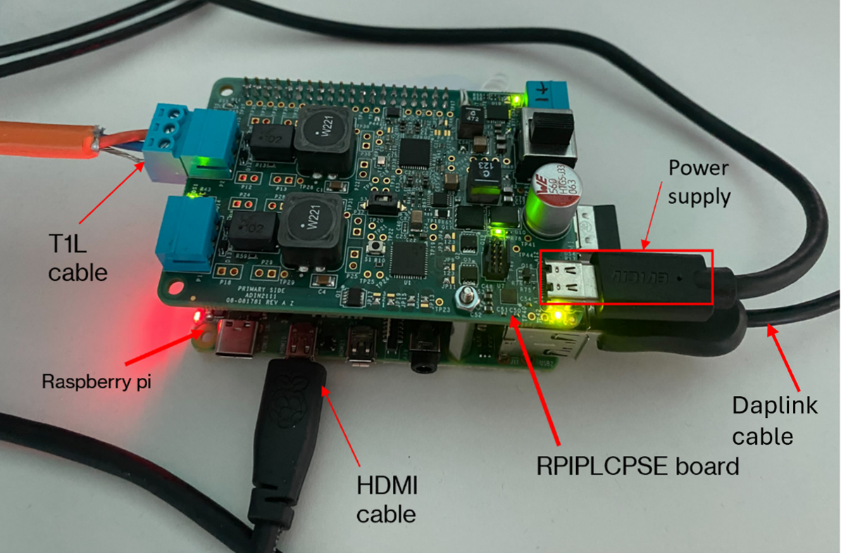
Required Setup
Insert the SD card into the Raspberry Pi.
Connect the Raspberry Pi to a monitor, keyboard, and mouse.
Insert the AD-RPI-T1LPSE-SL on top of the Raspberry Pi.
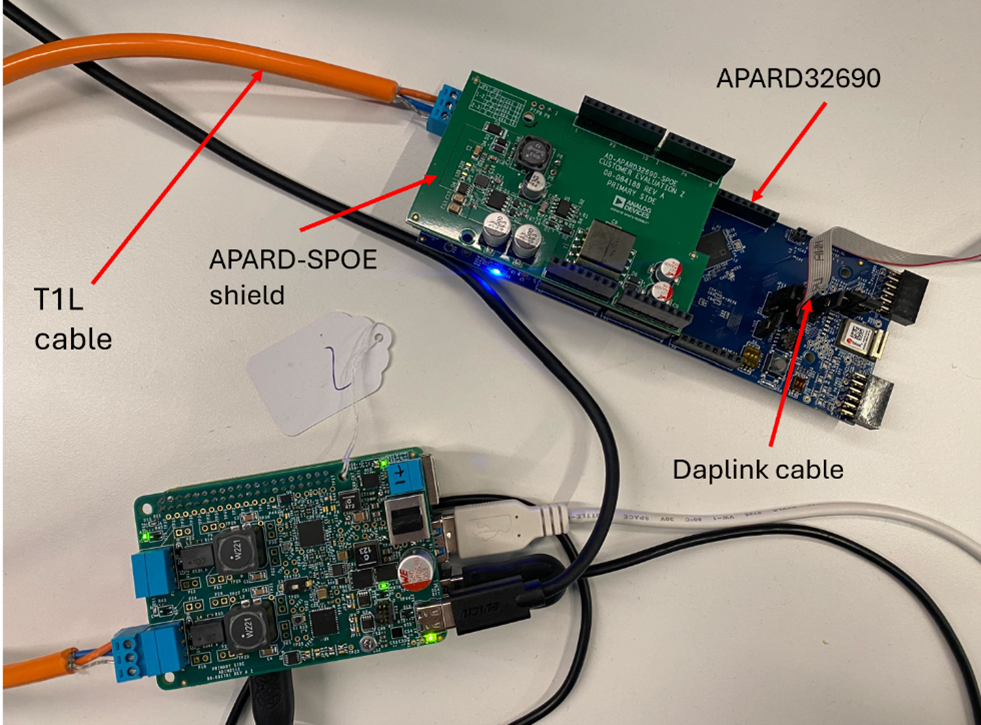
Connect the AD-APARD32690-SPOE shield on top of the AD-APARD32690-SL board.
Connect the T1L cable to AD-RPI-T1LPSE-SL and the AD-APARD32690-SL board.
Connect the DAPLink cable to the AD-APARD32690-SL board and plug it into the Raspberry Pi.
Power the AD-RPI-T1LPSE-SL using a Type-C power supply (12V).
Test Process
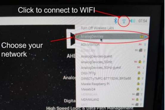
Wi-Fi Setup
Make sure the Raspberry Pi is connected to Wi-Fi before starting the tests.
Running the Tests
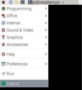
After the Raspberry Pi reboots, the test screen will appear on the monitor.
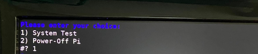
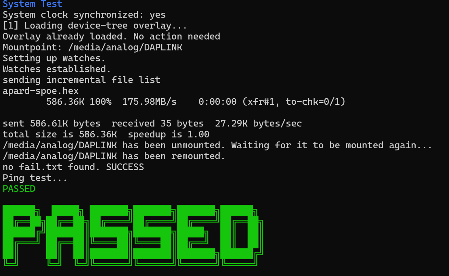
1) System Test
Type 1 into the terminal then press ENTER to start “1) System Test”. Connect the T1L cable to port 1.
If the test is PASSED, the DUT is functional. Continue testing the other boards.