Production Testing
Overview
The purpose of the test procedure is to identify connectivity issues, poor soldering, and potential manufacturing defects. Some of the issues are directly identified by explicit part-targeted tests, others are implicit, by running adjacent tests.
Note
Before production testing the AD-RPI-T1LPSE-SL board, the FTDI chip needs to be programmed. See the FTDI Programming section below.
FTDI Programming
Programming the board is done using the MAX77958_2S3 software, which can only be installed on Windows.
Required Hardware
Raspberry Pi used for production testing
1 x PC with Windows 10
MAX77958EVKIT-2S3 V1.0.0
Usb Type-C cable
MAX32625PICO (Daplink programmer)
Usb to I2C adapter board
Required Software
secure_update_BC58_verD005.bin- binary file containing the firmwareMAX77958EVKIT-2S3 V1.0.0 installed on Windows 10 - available from the ADI Software Download page
Required Setup

Programming Procedure
Power the device under test and make sure S2 switch is in position as shown in the image above.
Connect the mini programmer to the PC and open the MAX77958EVKIT-2S3 V1.0.0 application. This step can be done only once and the app can be kept open for programming the next board.

In the opened app, connect to the test board by clicking on Device -> Connect -> Yes -> Read and Close.
In the opened MAX77958_2S3 app, click on Tools -> Firmware Update… -> Open -> select
secure_update_BC58_verD005.binin the folder where it is saved -> Open -> Start.
Wait for the board to be programmed until the “…Completed” message is displayed.

Disconnect the board from MAX77958_2S3 application by clicking Device -> Disconnect.
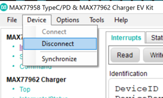
Figure 5 How to disconnect the board from MAX77958_2S3 application
After disconnecting the board from the PC, follow the instructions in the testing procedure below.
Test Duration
Step Description |
Estimate Time (minutes) |
|---|---|
Test bench setup |
3 min |
Software test |
5 min |
Total time |
8 min |
Test Requirements
Required Hardware
Raspberry Pi 4
HDMI cable
Mouse and keyboard
AD-RPI-T1LPSE-SL (Device Under Test)
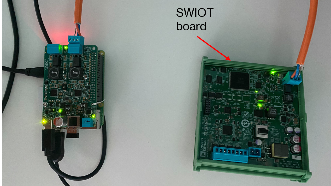
T1L cable and AD-SWIOT1L-SL board
12V power supply Usb Type-C
Required Software
The test image is provided on a pre-configured SD card.
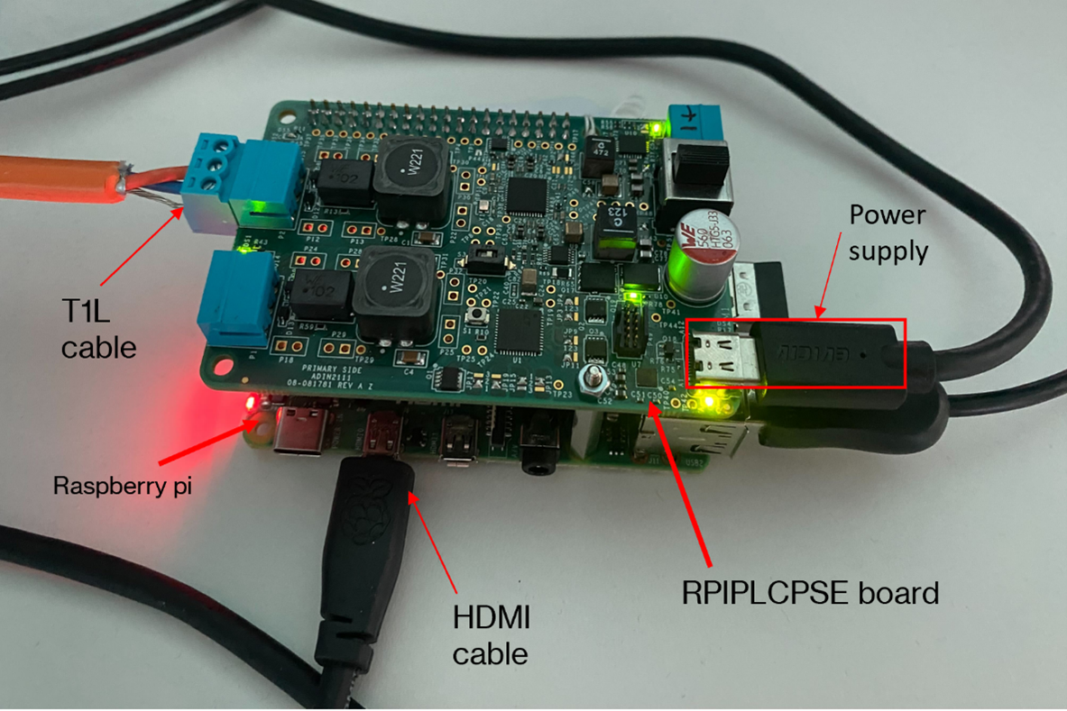
Required Setup
Insert the SD card into the Raspberry Pi.
Connect the Raspberry Pi to a monitor, keyboard, and mouse.
Insert the AD-RPI-T1LPSE-SL on top of the Raspberry Pi.
Connect the T1L cable to AD-RPI-T1LPSE-SL and the AD-SWIOT1L-SL board.
Power the AD-RPI-T1LPSE-SL using a Type-C power supply (12V).
Test Process
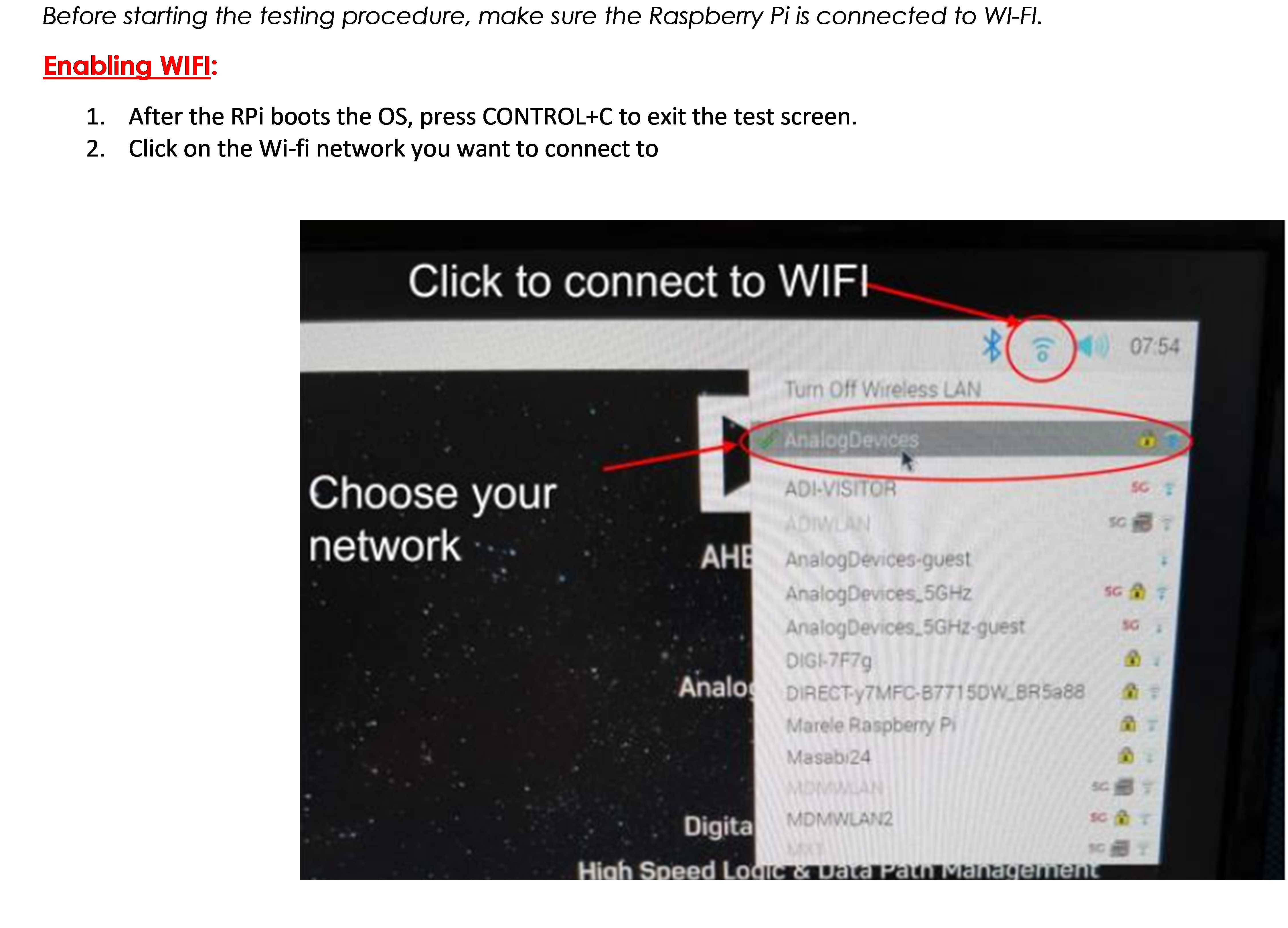
Wi-Fi Setup
Make sure the Raspberry Pi is connected to Wi-Fi before starting the tests.
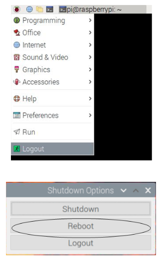
Running the Tests
After the Raspberry Pi reboots, the test screen will appear on the monitor.
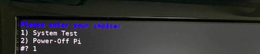
1) System Test
Type 1 into the terminal then press ENTER to start “1) System Test”.

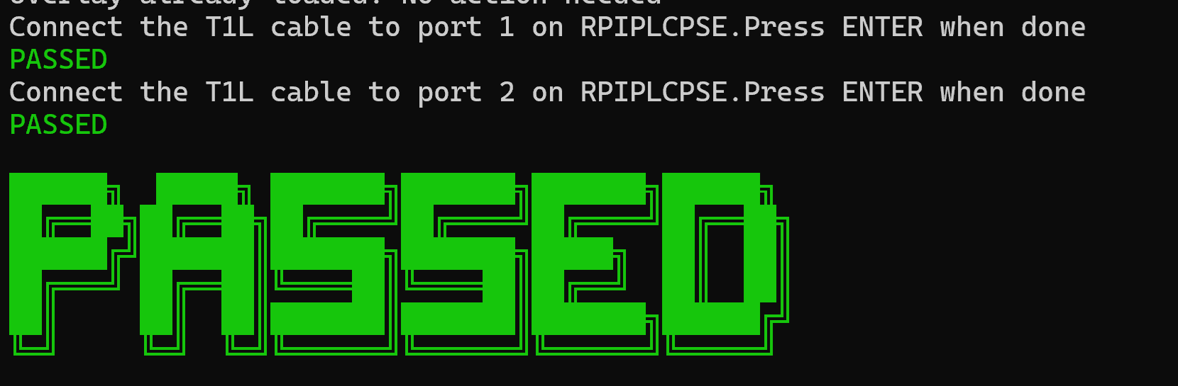
Connect the T1L cable to port 1.

If the test is PASSED, the DUT is functional. Continue testing the other boards.