ADRD3161-01Z Production Testing
Overview
The purpose of the test procedure is to identify connectivity issues, poor soldering, and potential manufacturing defects. Some of the issues are directly identified by explicit part-targeted tests, others are implicit, by running adjacent tests.
Test Duration
Step Description |
Estimated Time (minutes) |
|---|---|
Test bench setup |
8 min |
Software test |
6 min |
Total time |
14 min |
Test Requirements
Required Hardware
Raspberry Pi 5, power supply
HDMI cable, mouse, keyboard
1x USB to CAN adapter
1x CAN cable
1x motor QSH5718-76-28-101-10k
1x encoder cable
1x MAX32650 (DAPLINK programmer)
1x Power supply for device under test, crimped power cable
ADRD3161-01Z as device under test (D.U.T.)
SD card with the test image
Required Software
The test image will be provided as a SD test card that goes into the Raspberry Pi.
Required Setup
No. |
Steps |
|---|---|
1 |
Insert the SD card into the Raspberry Pi |
2 |
Connect the Raspberry Pi to a monitor and power it |
3 |
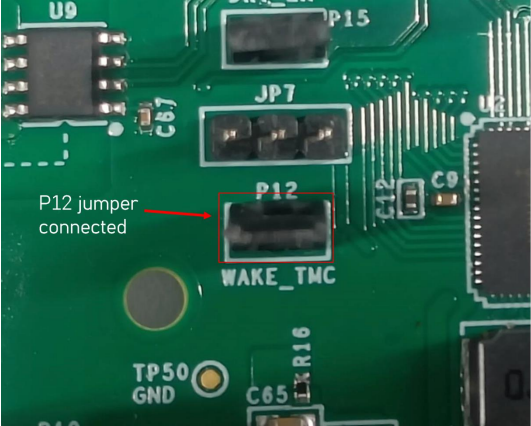
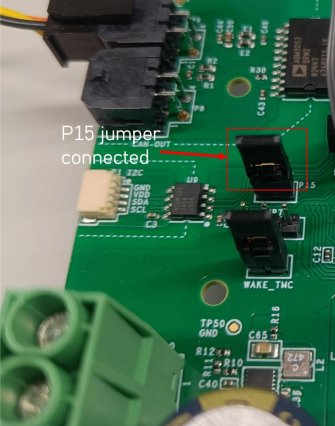
Put jumpers on D.U.T. P12, P15 in position |
5 |
Connect the CAN cable to P9 and the USB into the Raspberry Pi |
6 |
Connect the encoder cable between P16 and the motor |
7 |
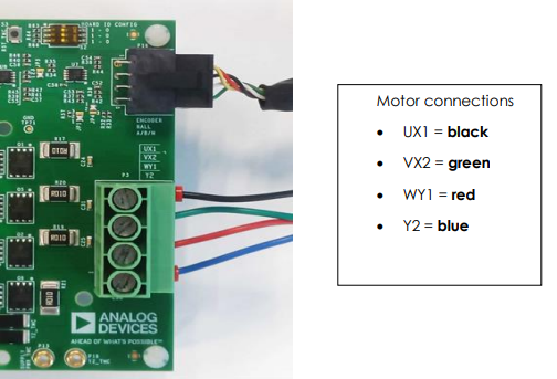
Connect the motor cable to P3 header (see picture below) |
8 |
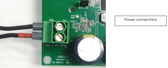
Connect power supply to P10 on D.U.T. board |
9 |
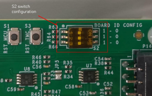
S2 switch in configuration shown in picture below |
10 |
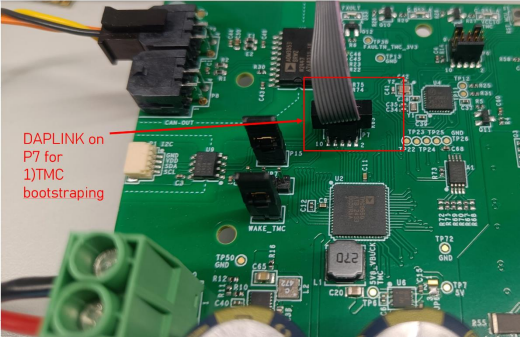
Connect the DAPLINK cable to P7 connector |
11 |
Run 1) TMC bootstrapping |
12 |
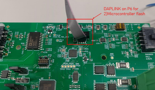
Move the DAPLINK to P6 connector |
13 |
Run 2) Microcontroller Flash |
14 |
Run 3) System test |
Note
When running test 1) Bootstrapping TMC, the DAPLINK should be connected to P7 connector
When running test 2) Microcontroller Flash and 3) System Test, the DAPLINK should be connected to P6 connector
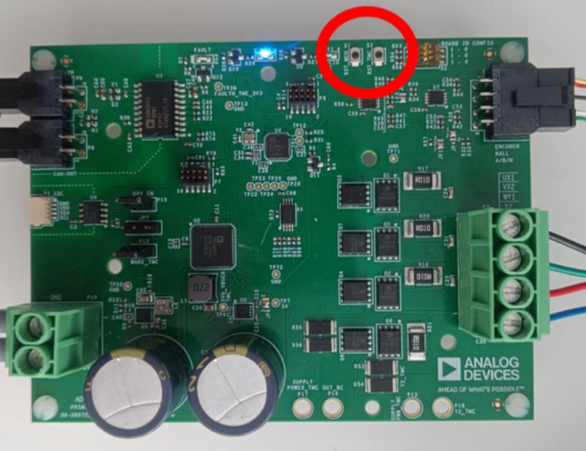
Jumper Positions
S2 Switch Configuration
Motor and Encoder Connections
When connecting the motor cable to P3, ensure the correct color order:
UX1 = black
VX2 = green
WY1 = red
Y2 = blue

DAPLINK Connections
Power Connections
Complete Test Bench

Test Process
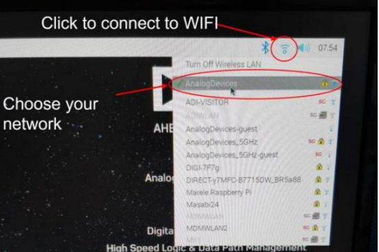
Before starting the testing procedure, make sure the Raspberry Pi is connected to Wi-Fi.
Enabling Wi-Fi
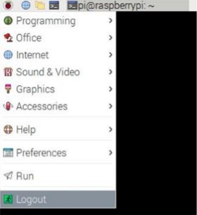
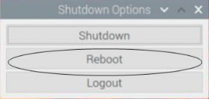
Running the Tests
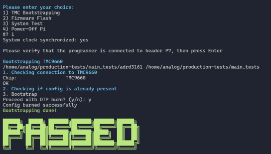
The following test menu should appear after reboot:
Please enter your choice:
1) TMC Bootstrapping
2) Firmware Flash
3) System Test
4) Power-Off Pi
1) TMC Bootstrapping
Type “1” and press ENTER to run 1) TMC9660 Bootstrapping. This step may fail once, in which case try it again. If it fails twice then either:
The board has already been through this test (check if any LEDs light up on the board)
The board is defective

When prompted Proceed with OTP burn? (y/n):, press y then ENTER.
Attention
1) TMC Bootstrapping test is a one-time step. It might fail if you run it multiple times. Thus, an error may be acceptable if the step was already run and passed in the past.
To diagnose whether an error in this test is an actual fault, or just a result of running the step multiple times, do the following:
Press TMC_RST -> check DS1 lights up
Press MCU_RST -> check DS1 turns off
After pressing RST_TMC |
After pressing RST_MCU |
Diagnosis |
|---|---|---|
DS1 lights up |
DS1 turns off |
OK! Both TMC and MCU are functional. |
DS1 lights up |
DS1 stays on |
TMC bootstrapped, MCU not functional (could be because step 2 didn’t run yet) |
DS1 LED does not turn on |
/ |
TMC fault/TMC not bootstrapped |
After TMC Bootstrapping:
Press RST_TMC button
Press RST_MCU button
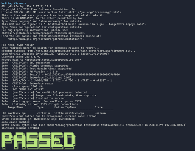
2) Firmware Flash
Type “2” in order to run 2) Firmware Flash. Connect the DAPLINK cable to P6 connector.
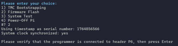
When prompted, verify that the programmer is connected to header P6, then press Enter.
3) System Test
Type “3” to run 3) System Test.
Warning
THE MOTOR WILL MOVE during this test.
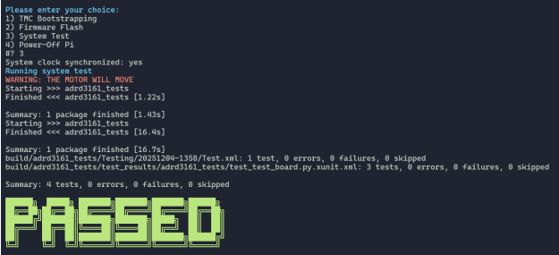
If test 3) fails, it will display:
