Production Testing
Overview
The purpose of the test procedure is to identify connectivity issues, poor soldering, and potential manufacturing defects. Some of the issues are directly identified by explicit part-targeted tests, others are implicit, by running adjacent tests.
Test Duration
Step Description |
Estimate Time (minutes) |
|---|---|
Test bench setup |
5 min |
Software test |
5 min |
Total time |
10 min |
Test Requirements
Required Hardware
Raspberry Pi 4
HDMI cable
AD-RPI-T1LPSE-SL board
1 x AD-APARD32690-SL board
1 x AD-SWIOT1L-SL board
MAX32625PICO (DAPLink programmer)
2 x T1L cables
1 x 12V power supply
1 x AD-APARDPFW-SL (Device Under Test)
Required Software
The test image is provided on a pre-configured SD card.
1 x SD card with the test image
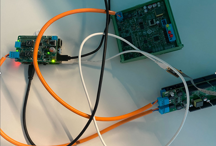
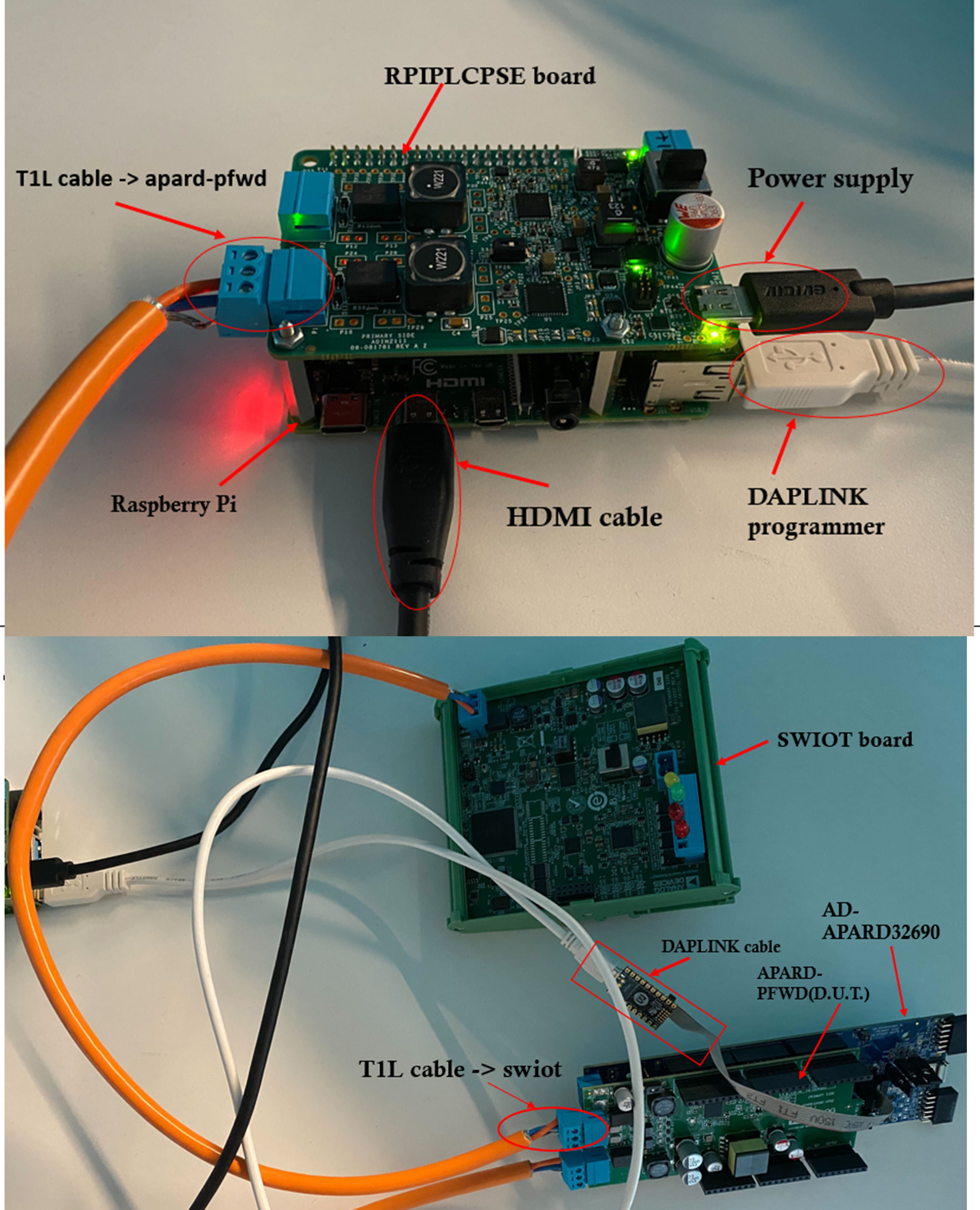
Required Setup
Insert the SD card into the Raspberry Pi.
Connect the Raspberry Pi to a monitor.
Connect the AD-RPI-T1LPSE-SL on top of the Raspberry Pi.
Connect the AD-APARDPFW-SL on top of AD-APARD32690-SL.
Connect the AD-RPI-T1LPSE-SL using a T1L cable to AD-APARDPFW-SL board port P7.
Connect the AD-SWIOT1L-SL to AD-APARDPFW-SL board port P8 using a T1L cable.
Connect the DAPLink programmer to the Raspberry Pi and to the AD-APARD32690-SL board.
Power the Raspberry Pi through AD-APARDPFW-SL using a 12V power supply.
Test Process
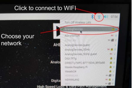
Wi-Fi Setup
Make sure the Raspberry Pi is connected to Wi-Fi before starting the tests.
Running the Tests
After the Raspberry Pi reboots, the test screen will appear on the monitor.
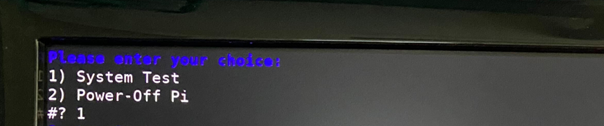
1) System Test
Type 1 into the terminal then press ENTER to start “1) System Test”.
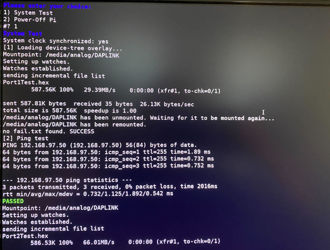
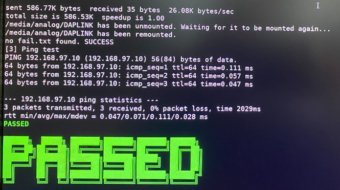
If the test is PASSED, the DUT is functional. Unplug it from the AD-RPI-T1LPSE-SL, then from the AD-APARD32690-SL board, and connect the next device under test.
Attention
If at any point the test fails, retry testing for up to 3 times before considering the board defective.