Dealing with non-Quadrature Signals
Quadrature signals can be broken down into two orthogonal components, I (in-phase) and Q (quadrature). Real or non-quadrature signals are technically a subset of quadrature when the components are in-phase or one of the components is zero.
Creating and Transmitting a “real” signal
There are two main ways to create and transmit a “real” signal:
Sending in-phase (or identical) I & Q signals
Sending just I or Q
Sending the same signal on I and Q
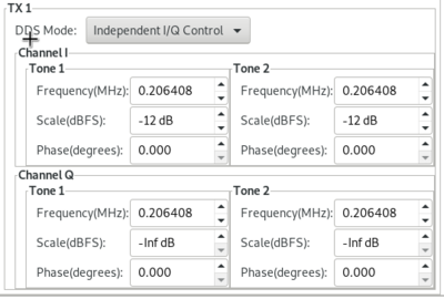
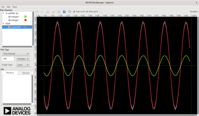
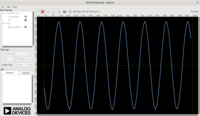
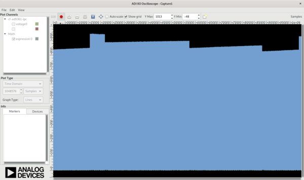
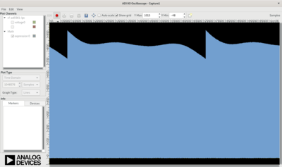
Using IIO-Scope, we can generate two tones, one on each DAC, both at the same frequency and magnitude.
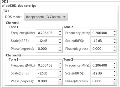
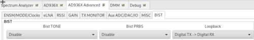
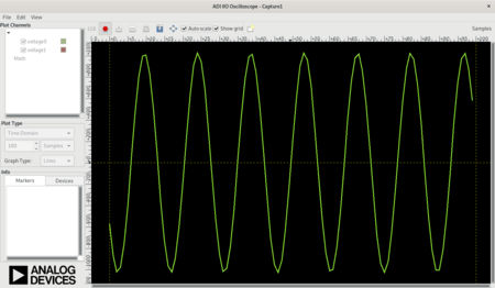
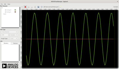
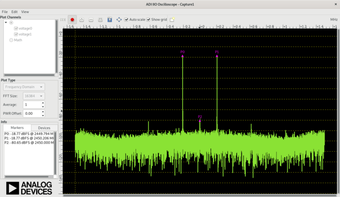
According to Euler’s formula, this should generate an equal-sized tone on each side of the LO. Using digital loopback, we can see that the math holds true.
Sending only I or only Q
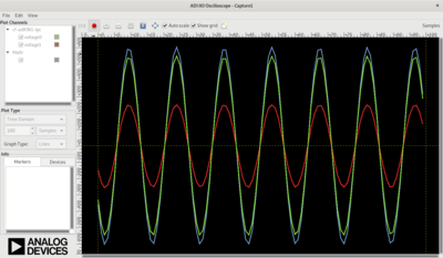
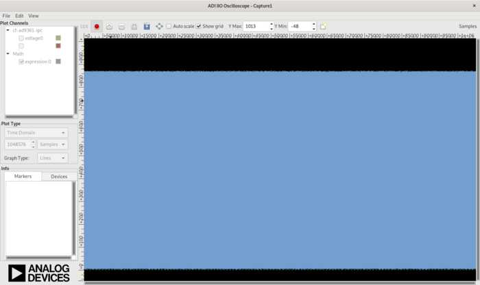
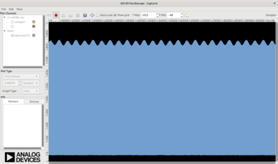
We can achieve the same thing, by only sending I or Q. In this case, we set the Q magnitude to -99 (or infinite attenuation).
We can see the same thing in the digital loopback.
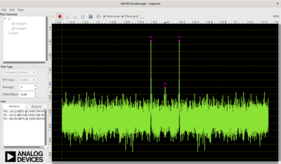
The one thing to notice is that the power in the signal is less (the peaks in the FFT drop), since we are sending half the power.
Receiving a “real” signal
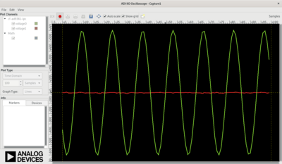
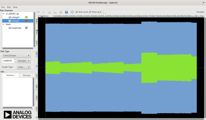
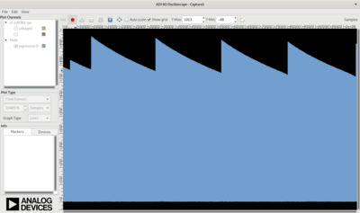
Most (all) integrated transceivers include some sort of Quadrature tracking corrections which try to ensure the signals are correct. There is no way for a Quadrature tracking correction algorithm to understand if a “real” signal is being sent (rather than an unwanted image). When the Rx and Tx LO are at the same frequency, this causes the amplitude is jumping up and down by a few dB.

The amplitude difference between I & Q is random based on the random difference between the phase of the Rx and Tx PLL. Every time you change the LO-frequencies, it changes.
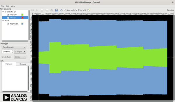
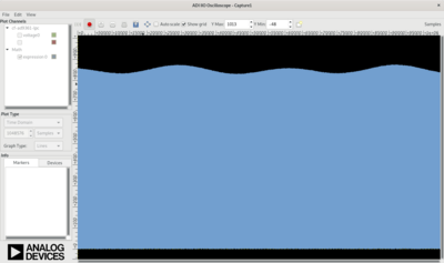
If you calculate magnitude with: sign(I) * sqrt(I² + Q²) you can ignore the
difference between I and Q, and remove any I/Q imbalance.
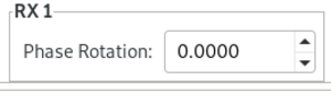
Rotation |
0 |
50 degrees |
70 degrees |
|---|---|---|---|
I/Q Plot |
|
|
|
Mag only |
|
However, the magnitude still has a step in it. This is because the RX Quadrature tracking state machine may or may not interact with the AGC state machine. It can be hard to tell what is causing the changes.
If we turn the AGC off (and use manual mode), we can see that it’s just the Quadrature tracking that is causing the issue.
Removing issues
The easiest way to remove this error is to simply turn off Quadrature tracking corrections. There are two main ways to do this:
Turning Quadrature tracking off
Offset Tuning
Turning Quadrature tracking off
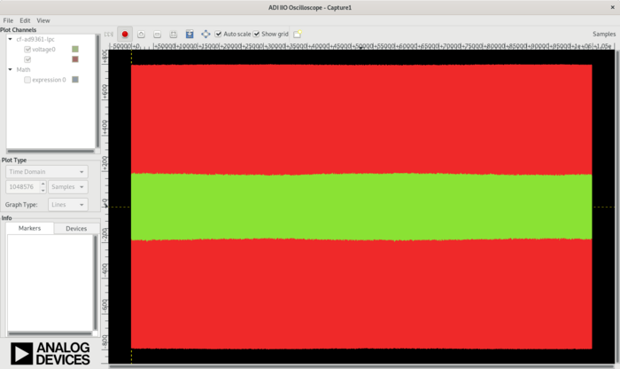
In IIO-Scope, this is done with a single attribute, called
quadrature_tracking_en.
This removes the magnitude step.
On USRP and
UHD, there is a
method
called set_rx_iq_balance() which does the same thing as the
AD9361 PHY quadrature_tracking_en attribute.
Offset Tuning
Instead of turning off Quadrature tracking (which is normally required), we can make sure that the Rx and Tx PLLs have a frequency offset greater than 10 Hz. For most standards, there is always a frequency offset in place, so this won’t be an issue. For simple loopback - it can be a PITA.
To check the offset, you can use:
analog@analog:~$ iio_attr -a -c ad9361-phy RX_LO frequency
dev 'ad9361-phy', channel 'altvoltage0' (output), id 'RX_LO', attr 'frequency', value '2400000000'
analog@analog:~$ iio_attr -a -c ad9361-phy TX_LO frequency
dev 'ad9361-phy', channel 'altvoltage1' (output), id 'TX_LO', attr 'frequency', value '2400000000'
To manually make an offset:
analog@analog:~$ iio_attr -D ad9361-phy loopback 1
iio_attr -D ad9361-phy loopback : SUCCESS (1)
analog@analog:~$ iio_attr -c ad9361-phy voltage0 gain_control_mode manual
dev 'ad9361-phy', channel 'voltage0' (input), attr 'gain_control_mode', value 'manual'
analog@analog:~$ iio_attr -c ad9361-phy voltage0 quadrature_tracking_en 1
dev 'ad9361-phy', channel 'voltage0' (input), attr 'quadrature_tracking_en', value '1'
With a 1kHz offset:
We can see that at 10 Hz offset, the Quadrature tracking correction works properly.
Offset |
Quadrature Tracking Off |
Quadrature Tracking On |
|---|---|---|
0 Hz |
|
|
5 Hz |
|
|
10 Hz |
|
|
20 Hz |
|
|


At 2.4 GHz, a sub 10 Hz offset would be better than 4 parts per billion (or 0.004 ppm) offset. This is pretty good.
Conclusion
This is not an ADALM-PLUTO issue. It will be an issue with all integrated devices which have some sort of Quadrature tracking feature (not just from ADI - but from all manufactures). The easiest thing to do is check your settings (to make sure it’s off, or on - if you know you need it).
SDRangel
With SDRangel, there are easy to use buttons:

RFDC - RF DC correction
BBDC - Baseband DC correction
IQ - RX Quadrature correction